IMPORTANT WARNING
Before carrying out the isolation test of the electrical panel the control unit is installed on, disconnect it together
with the sensors from the power supply, to prevent it from being seriously damaged.
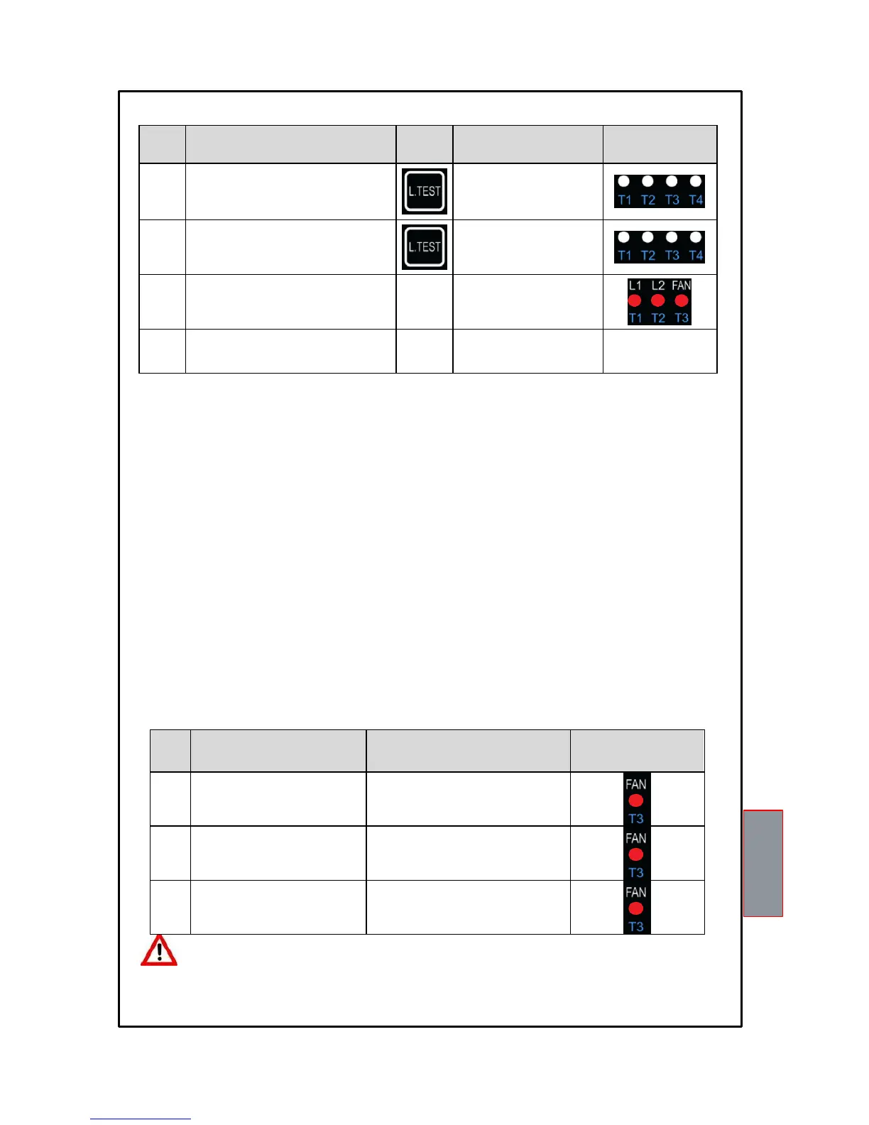
LED TEST
We suggest carrying out the control unit LED test regularly.
For this operation, press the TEST key briefly; all the LEDs light up for 2 seconds.
If one of the LEDs does not work, please return the control unit to TECSYSTEM for repair.
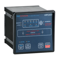
ALARM 1 RELAY OPERATION
The ALL1 (L1) relay operates normally when the unit is powered, therefore the N.O. contact is closed. In case of an alarm
on the ALL1 (L1) PTC or a fault in the control unit itself, the relay gets de-energised with consequent closing of the N.C.
contact.
The ALL1 (L1) relay also has the same function as the PTC sensor FAULT. If this relay is triggered when the PTC sensor
FAULT LED is FLASHING, it means that there is an error in the reading of a PTC sensor. It is possible to find it, thanks to
a second LED flashing which corresponds to the fault channel.
ALARM 2 RELAY OPERATION
The ALL2 (L2) relay is normally de-energized and energizes when there is an alarm on the L2 PTC.
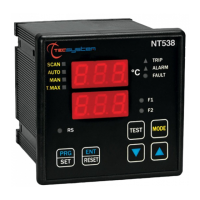
FAN RELAY OPERATION (VENTILATION)
During programming, it is possible to set the cooling time or to exclude the FAN option. If the FAN is excluded, the relay
doesn’t energize and for this reason it is possible not to install the corresponding PTC.
If the FAN is set up, the relay activates when the relative PTC sends the first signal and the FAN LED is steady ON: the
relay is active for as long as the PTC senses the temperature is normal, the T119 unit keeps the relay ON for the time set
during programming and the FAN LED flashes.
When the time expires and if the temperature is still normal, the relay de-energizes and the LED switches OFF.