4
91
F
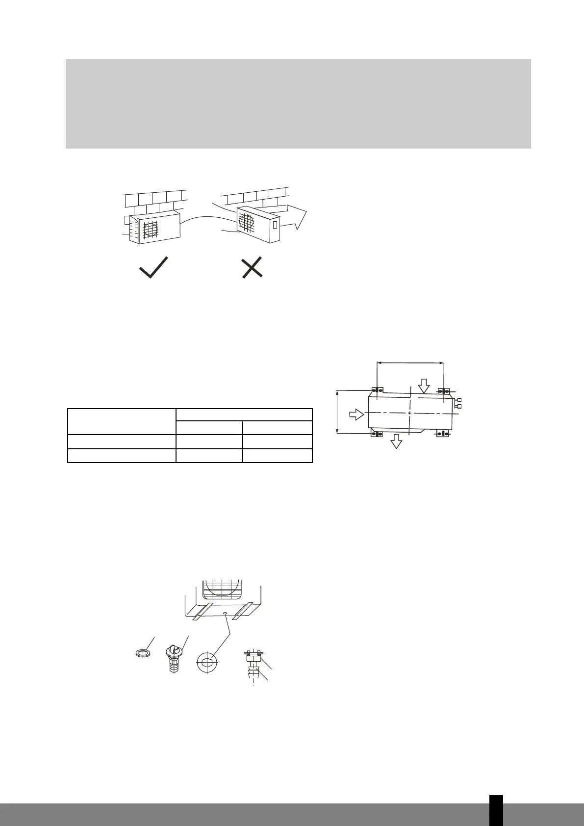
or capacities ≤ 7,0 kW: never place the outdoor unit over 5 meters higher or over 8 meters lower than the
indoor unit.
Fig. 12
Settlement of outdoor unit
Anchor the outdoor unit with bolts, lock washers and nuts ø 10 mm tightly and horizontally on a concrete
or rigid mount.
Fig. 13
Drain joint installation
(see fig. 14)
Fit the seal into the drain elbow, then insert the drain joint into the base pan hole in the bottom of the out-
door unit, rotate 90° to assemble them securely. Connect the drain joint with an extension drain hose (not
included). In this way condensed water, which is produced during heating mode of the airconditioner, can
be drained away.
Fig. 14
Outdoor unit
dimensions in mm
Mounting dimensions
A (mm) B (mm)
780x540x250 549 276
760x590x285 530 290
Air inlet
Air ourlet
Air inlet
Strong
wind
Seal
Drain joint
Base pan hole of
outdoor unit
Seal
Drain pipe
G
ATTENTION
If need suspending installation, the installation bracket should accord with all technical
requirements. The installation wall should be strong enough or actions to reinforce should be
taken. The connection between bracket and wall, bracket and the air conditioner should be firm,
stable and reliable. In case of any doubts or uncertainty do not attempt to install the unit but
have the support calculated and engineered by a skilled engineer.
 Loading...