Maintenance (Continued)
7. Slide the first impeller onto the shaft;
follow it with the impeller spacer.
Twist the impeller on the shaft to
make sure that the shaft key is still in
place and the impeller is locked to
the shaft (the shaft should turn with
the impeller).
8. Install a new volute gasket, lining up
the bolt holes with the bolt holes in
the adapter. Make sure the gasket is
right side up so that the water
passage holes line up with the water
passages in the volutes.
9. Install the intermediate volute,
aligning it with the mark made
before disassembly. Use the long cap
screws to check this alignment.
IMPORTANT: It cannot be stressed too
strongly that all bolt holes and water
passages of all gaskets and volutes
MUST line up with each other, or the
pump will not be assembled correctly.
10.Make sure the second shaft key is in
place and install the second
impeller. Twist the impeller to make
sure that the shaft key is still in
place. Hold the motor shaft with
slip-joint pliers or vice-grips and
install and tighten the impeller
locknut. Tightening the locknut
automatically spaces the impeller
correctly. Do not overtighten.
11.For Model No. 4RJ96A, repeat Steps
7 through 10 for the second
intermediate volute.
12.Install the base volute gasket. Make
sure the gasket is right side up so
that the water passage holes line up
with the water passages in the
volutes. Install the base volute,
using the alignment marks made
before disassembly. Make sure that
the pump discharge will correctly
meet the piping when the pump is
reinstalled.
13.Insert the four base capscrews and
tighten evenly (See Figure 19). These
should be easy to install if
everything is correctly aligned. If
not, don’t force them; go back over
your work and find and correct the
misalignment.
14.Reinstall the pressure switch barb
fitting and pressure tube.
15.Reinstall the pump on the adapter
flange (use a new gasket) and
reconnect the wiring and
grounding. Pump is now ready for
operation.
PUMP DISASSEMBLY/ ASSEMBLY
FOR SINGLE STAGE PUMP
MODEL NOS. 4P037, 4P038, 4P039
1. Turn OFF the power to the pump at
the disconnect switch. Disconnect
power lines from pressure switch.
2. Remove the discharge piping to the
pump.
3. Remove the cap screws holding the
adapter to the volute. Don’t disturb
the piping to the well.
4. Lift the pump motor and adapter
straight up off of the volute.
5. Set the pump on a work bench on its
side. Be sure you block it so that it
cannot roll off the bench onto your
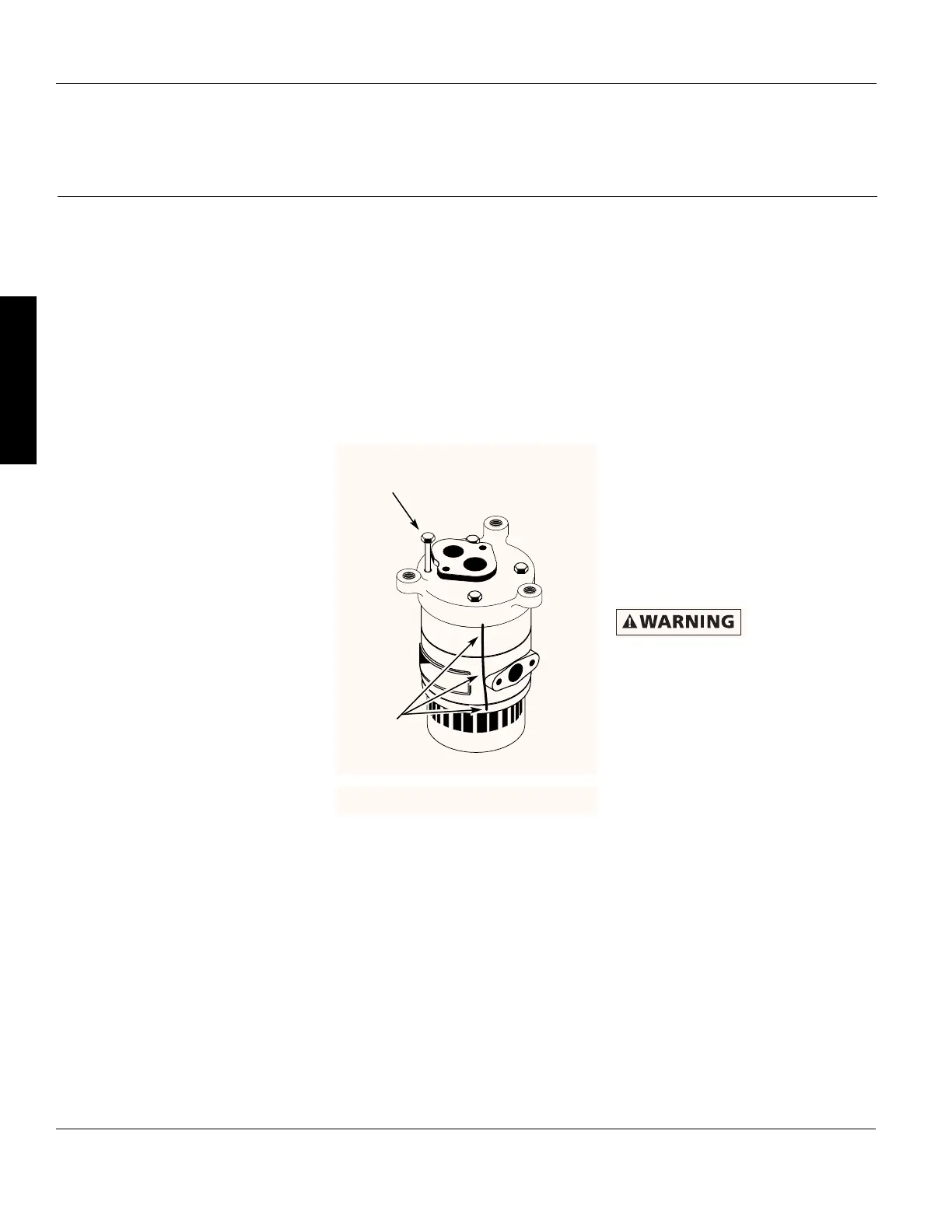
foot.
6. Remove the canopy (cover) from the
top of the motor to get at the motor
shaft and the capacitor.
Capacitor voltage
may be hazardous.
To discharge motor capacitor, hold
insulated handle screwdriver BY THE
HANDLE and short capacitor terminals
together. Do not touch metal screwdriver
blade or capacitor terminals. If in doubt,
consult a qualified electrician.
7. Unscrew capacitor clamp and remove
capacitor. Do not disconnect
capacitor wires to motor.
14
Teel Operating Instructions and Parts Manual
3P740A, 4P037, 4P038, 4P039 and 4RJ96A
Teel One, Two, and Three Stage
Vertical Jet Pumps
®
E
N
G
L
I
S
H
line up.
insert.
 Loading...