EasyManua.ls Logo

teel 3P740A - User Manual

teel 3P740A
22 pages
Print Icon
To Next Page IconTo Next Page
Loading...
F
R
A
N
Ç
A
I
S
E
S
P
A
Ñ
O
L
®
Teel One, Two, and Three
Stage Vertical Jet Pumps
Operating Instructions & Parts Manual 3P740A, 4P037, 4P038, 4P039 and 4RJ96A
Please read and save these instructions. Read carefully before attempting to assemble, install, operate or maintain the product described.
Protect yourself and others by observing all safety information. Failure to comply with instructions could result in personal injury and/or
property damage! Retain instructions for future reference.
Form 5S3773
®
E
N
G
L
I
S
H
Printed in U.S.A.
09319
0401/066/E3
4P037 1/2 12.4/6.2 115/230 1 60 1 230V 30-50 PSI 1
1
4”114
1
2”8
7
8”12
1
4 53 lbs.
4P038 3/4 14.8/7.4 115/230 1 60 1 230V 30-50 1
1
4 115
1
8 8
7
8 12
1
4 63
4P039 1 19.2/9.6 115/230 1 60 1 230V 30-50 1
1
4 116
3
16 8
7
8 12
1
4 65
3P740A 1 19.2/9.6 115/230 1 60 2 230V 30-50 1
1
4 117
3
4 8
1
2 12
1
4 70
4RJ96A 1
1
2 12.0 230 1 60 3 230V 30-50 1
1
4 120
7
16 8
1
2 12
1
4 84
Specifications
Motor Press. N.P.T.
Max Load Motor Conn. Switch Suc. Dis.
Dimensions
Model HP Amps Volts PH Hz Stages for Sett. Inlet Out H W L Wt
20
100
80
60
40
Description
Teel one, two, and three stage vertical jet pumps Model Nos. 3P740A, 4P037,
4P038, 4P039 and 4RJ96A are designed for deep well installations. With a deep well
ejector installed, the vertical jet pumps can be used on wells with water levels to
300 feet deep (depending on pump and ejector package used). Pumps are
equipped with capacitor start motor and 30-50 psi preset pressure switch. Motor
RPM is 3450.
Unpacking
Open carton and remove unit. Check for
loose, missing, or damaged parts.
See Parts List.
Question and Answer IconNeed help?

Do you have a question about the teel 3P740A and is the answer not in the manual?

Summary

General Safety Information

Safety Alert Symbol and Warnings

Explains the safety alert symbol and different hazard warning levels like DANGER, WARNING, and CAUTION.

Electrical Safety

Details about electrical hazards, capacitor voltage warnings, and proper wiring practices.

Installation

Replacing an Existing Pump

Steps for installing a new pump when replacing an old one, including compatibility checks.

Piping in the Deep Well

Instructions and notes for deep well piping configurations, including pipe types and ejector placement.

Plastic Pipe Installation - Double Pipe

Specific guidance for installing plastic pipes in double pipe systems, emphasizing Teflon tape use.

Single Pipe Ejector Installation

Guidelines for installing ejectors in single pipe deep well systems, including pipe material and coupling types.

Discharge Pipe Sizes

Information regarding correct discharge pipe sizing for pumps based on run length.

Pressure Tank Installation

Guidance on installing pressure tanks to maintain water pressure and prevent hammering.

Sealing Pipe Joints

Instructions for ensuring airtight and watertight seals on suction pipe joints using Teflon tape.

Electrical Installation

Wiring Connections

Explains correct wiring practices, voltage conversion, and grounding requirements for motors.

Connection Procedure

Step-by-step guide for connecting the pump's electrical system, including grounding and power supply.

Operation

Priming the Pump

Step-by-step instructions on how to properly prime the pump before operation to ensure water flow.

Handling a Gaseous Well

Methods for dealing with wells that produce gaseous water to ensure delivery of gas-free water.

Air Control in Flowing Wells

Addresses air control issues in flowing wells and recommends pre-charged tanks for better operation.

Maintenance

Pump Assembly;Disassembly

Detailed steps for taking apart and reassembling the pump for service, including impeller removal.

Installation of New Seal

Step-by-step instructions for cleaning and installing a new shaft seal, ensuring proper seating.

Single Stage Pump Disassembly;Assembly

Specific procedures for disassembling and assembling single-stage pump models, including capacitor removal.

Installing New Seal

Guide to installing a new seal, ensuring proper seating and alignment of the sealing surfaces.

Troubleshooting Chart

Motor Issues

Addresses common motor problems like not running, overheating, or tripping overload.

Water Delivery Problems

Diagnoses issues with no water delivery, low capacity, or pump not shutting off.

Pump Cycles Too Frequently

Identifies causes for frequent pump cycling, such as leaks or low air charge.

Air Spurts from Faucets

Explains reasons for air spurts, including priming issues, suction leaks, or gaseous wells.

Overview

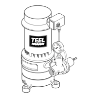
The Teel One, Two, and Three Stage Vertical Jet Pumps, including Model Nos. 3P740A, 4P037, 4P038, 4P039, and 4RJ96A, are designed for deep well installations. These pumps are capable of operating in wells with water levels up to 300 feet deep, depending on the specific pump and ejector package used. Each pump is equipped with a capacitor start motor and a pressure switch preset to a 30-50 psi range, with the motor operating at 3450 RPM.

Function Description

The primary function of these vertical jet pumps is to draw water from deep wells. In a deep well installation, an ejector package is installed within the well, which works in conjunction with the pump to lift water from significant depths. The pump's capacitor start motor provides the necessary power, and the pressure switch automatically controls pump operation to maintain water pressure within the specified range.

Usage Features

Installation:

Proper installation is crucial for optimal performance. The pump must be matched to the correct ejector and well depth, as detailed in the performance charts. Long pipe runs and numerous fittings should be avoided to minimize friction and maximize flow; therefore, the pump should be located as close to the well as possible. The well must be clear of sand, as sand can plug the pump and void the warranty. Protection against freezing is essential, as freezing can damage pipes and the pump, also voiding the warranty. All pipes and the foot valve must be clean and in good condition, and there should be no air pockets or leaks in the suction pipe. Teflon tape or Plasto-Joint Stik should be used to seal pipe joints. The flow into the well must at least equal the flow out through the pump. Unions installed near the pump and well facilitate servicing.

Deep Well Piping (Double Pipe - 4" or larger wells):

In double pipe installations, the larger pipe serves as the suction pipe, and the smaller pipe is the drive pipe. Plastic pipe is recommended for its light weight and ease of handling during installation and removal. Teflon tape should be used on all male threads to prevent air leaks. The ejector's nozzle and venturi openings must be clean. The casing adapter uses a gasket between itself and the pump flange. The well casing acts as the drive pipe, and the suction pipe draws water from the well. The ejector should be set 10 to 20 feet below the lowest water level with the pump running, if possible, but always at least five feet from the bottom of the well. Locating lugs on the adapter flange and pump base must be aligned to ensure proper piping alignment.

Deep Well Piping (Single Pipe - 2" wells):

Single pipe installations require galvanized steel pipe, a leather packer-type ejector with a built-in foot valve, turned couplings, and a well casing adapter. The ejector is connected to the first length of pipe using pipe joint compound sparingly on male threads. Special turned couplings are used to increase water flow. The pipe should be filled with water as each length is added to check for leaks. The ejector should be positioned at the proper depth, similar to double pipe installations. To properly seat the cup seals, the assembly should be moved up and down slightly after positioning, allowing water pressure to soak the seals, which typically seal within 2-3 hours.

Discharge Pipe Sizing:

If the discharge pipe size is increased, a reducer should be installed in the pump discharge port. The pipe size should not be increased in stages. For runs up to 100 feet, use the same size as the pump discharge port. For runs between 100 and 300 feet, increase the pipe size by one. For runs between 300 and 600 feet, increase the pipe size by two.

Pressure Tank Installation:

The pressure tank provides a water reservoir and maintains air pressure to prevent pipe hammering.

  • Standard Tank Connection: An air volume control (AVC) adds air to the tank as needed. The AVC connects to a 1/4" compression fitting on the front of the pump.
  • Precharged Tank Connection: No AVC is necessary with a precharged tank, which comes with a factory-provided air charge. The pump pressure switch is set for a 30-50 psi range, requiring a tank pre-charge of 28 psi for proper operation. An annual check of the tank air charge is recommended.

Electrical Installation:

Hazardous voltage is present, so disconnect power before working on the pump, motor, pressure switch, or wiring. The motor terminal board and pressure switch connections must match the line voltage. Dual-voltage motors are factory-wired for 230 volts but can be reconnected for 115 volts if necessary. All wiring must comply with the National Electrical Code, Canadian Electrical Code, and local codes. A solid copper ground wire, at least as large as the power supply wires, must be connected first, linking the pressure switch to the motor and then to a grounded lead in a service panel, an underground water pipe, a well casing, or a ground electrode.

Priming the Pump:

Never run the pump dry, as this can cause overheating, damage the seal, and lead to burns. Open water system faucets before priming. Remove the pressure gauge, close the regulator valve (turn clockwise), and fill the pump and suction pipe with water. Replace and tighten the pressure gauge. If a priming tee and plug are present for a long horizontal run, fill the suction pipe through it. Start the pump; pressure should build rapidly to 50 psi or more. If no pressure or water, repeat priming two or three times. If still no water, check that the suction pipe is in the water and has no leaks. Air leaks can occur even where water doesn't leak out, so ensure all joints are tight.

Operation:

Once the unit has primed and pressure stabilized, slowly open the regulator valve (turn counterclockwise) until the pressure falters (gauge needle flutters, pump becomes noisy). Then, close the regulator valve slightly until pressure stabilizes; this setting provides maximum flow. The pump may draw the well down, potentially losing prime; if so, close the regulator valve until pressure is stable throughout the pumping cycle, then close faucets and allow the pump to pressurize and shut off. Check the system by alternately opening and closing faucets. In some deep well operations, the regulator valve may be completely open without pressure faltering.

Gaseous Wells:

For wells with gases, suspend a pipe, closed at the bottom and open at the top, around the suction pipe inlet. This allows gases to rise in the well casing, ensuring gas-free water is drawn into the pump. The well must be vented to the outside.

Air Control in Flowing Wells:

For flowing wells or wells with little drawdown, a pre-charged tank (which does not need air control) is recommended for air control.

Maintenance Features

Pump Assembly/Disassembly (2-stage and 3-stage pumps):

  1. Turn off power at the disconnect switch and disconnect power lines from the pressure switch.
  2. Remove the two cap screws holding the pump to the flange adapter without disturbing well piping.
  3. Remove the flange adapter gasket and clean surfaces.
  4. Unscrew and remove the straight barbed fitting at the pressure switch, leaving tubing in place.
  5. Draw an index line down the side of the pump from the motor to the base volute to aid reassembly alignment.
  6. Turn the pump upside down, block it, remove the four base cap screws. Tap upward on the base with a mallet to loosen it, then lift the base off the intermediate volute.
  7. Lay the pump on a bench and block it to prevent rolling.
  8. Hold the motor shaft with pliers or vice grips through the pump adapter opening and unscrew the impeller nut.
  9. Impellers are keyed to the shaft; insert two screwdrivers on opposite sides under the exposed impeller and pry it off.
  10. Carefully tap a small screwdriver or thin chisel between the intermediate volute and pump adapter to separate castings, avoiding damage to sealing surfaces.
  11. Remove the intermediate volute and slide the impeller spacer off the shaft.
  12. For Model No. 4RJ96A, repeat steps 9-11 for the second intermediate volute.
  13. Remove the impeller, but do not disturb shaft keys if only replacing the seal.
  14. Rotate the seal spring retainer cup to align with shaft keys, then remove the cup and spring.
  15. Remove the two cap screws holding the adapter bracket to the motor.
  16. Carefully pry the pump adapter away from the motor with two screwdrivers, which will pull the seal off the motor shaft. Be careful not to scratch the shaft's sealing surface with the ceramic seal.

Installation of New Seal:

  1. Clean all gasket surfaces and the seal bore cavity in the pump adapter.
  2. Wet the rubber seat ring with soapy water and push the stationary part of the seal into the seal bore cavity, using a 1" pipe and cardboard washer as a press. Ensure the seal half is fully seated.
  3. Ensure shaft keys are in place; squeeze them with slip joint pliers if needed, but do not tap them with a hammer to avoid bending the shaft. The adapter should pass over the keys without interference.
  4. Carefully slide the adapter over the shaft, avoiding damage to the highly polished shaft sealing surface.
  5. Align the adapter with the motor using the index marks made during disassembly and bolt it in place, tightening cap screws evenly.
  6. Push the shaft seal and seal spring onto the shaft (sealing face first), ensuring clean seal faces and shaft. Follow with the spring holder and compress the spring, giving it a quarter turn to lock it under the first shaft key.
  7. Slide the first impeller onto the shaft, followed by the impeller spacer. Twist the impeller to ensure the shaft key is in place and the impeller is locked to the shaft.
  8. Install a new volute gasket, ensuring bolt holes and water passages align correctly.
  9. Install the intermediate volute, aligning it with the disassembly mark. Use long cap screws to check alignment.
  10. Ensure the second shaft key is in place and install the second impeller. Twist the impeller to ensure the shaft key is in place. Hold the motor shaft with slip-joint pliers or vice-grips, install, and tighten the impeller locknut. Do not overtighten.
  11. For Model No. 4RJ96A, repeat steps 7-10 for the second intermediate volute.
  12. Install the base volute gasket, ensuring water passage holes align. Install the base volute, aligning it with the disassembly marks, ensuring the pump discharge meets the piping when reinstalled.
  13. Insert the four base cap screws and tighten evenly. If they don't install easily, check for misalignment.
  14. Reinstall the pressure switch barb fitting and pressure tube.
  15. Reinstall the pump on the adapter flange (using a new gasket) and reconnect wiring and grounding.

Pump Disassembly/Assembly (Single Stage Pump - Model Nos. 4P037, 4P038, 4P039):

  1. Turn off power at the disconnect switch and disconnect power lines from the pressure switch.
  2. Remove the discharge piping to the pump.
  3. Remove the cap screws holding the adapter to the volute, without disturbing well piping.
  4. Lift the pump motor and adapter straight off the volute.
  5. Set the pump on its side on a workbench, blocked to prevent rolling.
  6. Remove the canopy (cover) from the motor top to access the motor shaft and capacitor. Discharge the motor capacitor by shorting its terminals with an insulated handle screwdriver.
  7. Unscrew the capacitor clamp and remove the capacitor, but do not disconnect capacitor wires to the motor.
  8. Hold the motor shaft with a 7/16" end wrench on the motor flats and unscrew the impeller, exposing the seal.
  9. Pull the rotating half of the seal off the shaft with two screwdrivers, being careful not to mar the shaft.
  10. Remove four cap screws and remove the adapter from the motor. Place it face up on the bench.
  11. Pry loose the floating seat by applying a screwdriver between the seat and the cavity in the casting.
  12. Clean the casting cavity and the motor shaft.

Installing New Seal (Single Stage Pump):

  1. Clean the polished surface of the floating seat with a clean cloth.
  2. Wet the O-ring on the ceramic seat with soapy water.
  3. Press the seat firmly into the cavity with finger pressure. If needed, use a cardboard washer over the polished surface and press with a 3/4" standard pipe. Dispose of the cardboard washer and ensure the polished surface is free of dirt and damage.
  4. Reinstall the adapter on the motor, ensuring no damage to the seal when inserting the shaft.
  5. Inspect the shaft for cleanliness. Clean the face of the sealing washer.
  6. Apply soap solution to the inside diameter and outer face of the rubber drive ring. Carefully slide the seal assembly onto the shaft (sealing face first) until the rubber drive ring slides over the shaft shoulder. Avoid chipping or scratching the sealing surface.
  7. Hold the shaft flats with a 7/16" wrench and screw the impeller onto the shaft until the impeller hub hits the shaft shoulder. This automatically locates the seal and pulls the sealing washer face up against the floating seat face.
  8. Reassemble the pump in reverse order from disassembly.

teel 3P740A Specifications

General IconGeneral
Model3P740A
CategoryWater Pump
Inlet Size1 inch
Outlet Size1 inch
Frequency50 Hz
Power750W

Related product manuals