EasyManua.ls Logo

teel 4P847A - User Manual

Default Icon
16 pages
Print Icon
To Next Page IconTo Next Page
Loading...
F
R
A
N
Ç
A
I
S
E
S
P
A
Ñ
O
L
®
Teel Deep Well
Submersible Pump
Operating Instructions & Parts Manual
Please read and save these instructions. Read carefully before attempting to assemble, install, operate or maintain the product described.
Protect yourself and others by observing all safety information. Failure to comply with instructions could result in personal injury and/or
property damage! Retain instructions for future reference.
Form 5S3421
®
Description
Teel deep well submersible pumps are designed for use in 4” (or larger) interior
diameter wells in home, farm, and industrial deep well applications. Units include
pump and motor completely assembled. Three wire units require a control box
which must be ordered separately.
Hazardous voltage. Can shock, burn, or kill. To reduce risk of
electrical shock, install pump in accordance with latest United
States National Electrical Code (NEC), Article 250. Connect motor grounding wire (green
wire) to power supply system ground using copper conductor at least as large as
conductors supplying power to motor.
Pump is designed for use in a water well supplying a domestic water system and
has not been investigated for use in other applications. Do not use this pump in
swimming pools.
Pumps 4RH01 thru 4RH06, 4RG76 thru 4RG84, 4RG94 thru 4RG97, and 4RG99 are
thermoplastic discharge.
Pumps 4P847A thru 4P851A and 4P852 thru 4P856 are cast iron discharge.
E
N
G
L
I
S
H
Printed in U.S.A.
09319
0798/116/E3
4P847A 1/3 10 3 4P840 5 115 60 9.2 1
1
/
4
4P848A 1/3 10 3 4P841 5 230 60 4.6 1
1
/
4
4RH03 1/2 13 2 5 115 60 12.0 1
1
/
4
4P849A, 4RG99 1/2 13 3 4P843 5 230 60 6.0 1
1
/
4
4P850A, 4RH04 1/2 13 2 5 230 60 6.0 1
1
/
4
4RH05 3/4 18 2 5 230 60 8.0 1
1
/
4
4P851A, 4RH01 3/4 18 3 4P844 5 230 60 8.0 1
1
/
4
4RH02 1 22 3 4P845 5 230 60 9.8 1
1
/
4
4RH06 1 22 2 5 230 60 9.8 1
1
/
4
4P852 1/3 4 3 4P840 10 115 60 9.2 1
1
/
4
4P853 1/3 4 3 4P841 10 230 60 4.6 1
1
/
4
4P854 1/3 4 2 10 230 60 4.6 1
1
/
4
4P855 1/2 6 3 4P842 10 115 60 12.0 1
1
/
4
4P856, 4RG76 1/2 6 3 4P843 10 230 60 6.0 1
1
/
4
4P857, 4RG80 1/2 6 2 10 115 60 12.0 1
1
/
4
4P858, 4RG81 1/2 6 2 10 230 60 6.0 1
1
/
4
4P859, 4RG77 3/4 8 3 4P844 10 230 60 8.0 1
1
/
4
4P860, 4RG82 3/4 8 2 10 230 60 8.0 1
1
/
4
4P861, 4RG78 1 10 3 4P845 10 230 60 9.8 1
1
/
4
4RG83 1 10 2 10 230 60 9.8 1
1
/
4
4RG84 1
1
2 14 2 10 230 60 13.1 1
1
/
4
4P862, 4RG79 1
1
2 14 3 4P846 10 230 60 11.5 1
1
/
4
4P863, 4RG94 1 7 3 4P845 20 230 60 9.8 1
1
/
4
4P864, 4RG96 1 7 2 20 230 60 9.8 1
1
/
4
4P865, 4RG95 1
1
2 9 3 4P846 20 230 60 11.5 1
1
/
4
4RG97 1
1
2 9 2 20 230 60 13.1 1
1
/
4
(*) Not included; order separately.
Specifications
Control Service
Motor Box Factor Discharge
Model HP Stages Wires Required* GPM Voltage Hz Amps Opening
Figure 1
4P847A thru 4P851A, 4P852 thru 4P865,
4RH01 thru 4RH06, 4RG76 thru 4RG84,
4RG94 thru 4RG97 and 4RG99
Question and Answer IconNeed help?

Do you have a question about the teel 4P847A and is the answer not in the manual?

Summary

Teel Deep Well Submersible Pump Manual

Product Description and Overview

Details the purpose, design, and applications of Teel deep well submersible pumps.

Model Specifications Table

Lists detailed technical specifications for various pump models, including HP, stages, voltage, and GPM.

Essential Safety Information

Electrical Hazard and Prevention

Covers warnings for hazardous voltage, grounding, and proper electrical work practices.

System Integrity and Environmental Safety

Addresses freezing prevention, ventilation for controls, and well seal maintenance.

Installation and Maintenance Best Practices

Recommends qualified personnel, preventive maintenance, and power cable protection.

General Safety Precautions

Operational and Equipment Safety

Focuses on control box safety, equipment protection, and pump application limitations.

Preinstallation Safety Checks

Emphasizes electrical supply verification, wiring checks, and cable size importance.

Cable Splicing and Handling

Details underwater cable splicing and safe handling of power cables.

Advanced Installation Procedures

Heat Shrink Splicing and Testing

Guides on heat shrink splicing for wires, including testing for continuity and insulation.

Pump Installation Fundamentals

Covers general pump installation, well preparation, and necessary tools.

Pump Installation and Well Preparation

Well Preparation and Data Collection

Details well casing inspection, chlorination, and collecting data for new installations.

Old Well Pump Replacement Guidelines

Provides guidance for replacing old pumps, including depth setting for jet pumps.

Old Equipment Removal Techniques

Describes methods and tools for removing old pumps and equipment from wells.

Pump Installation and Piping Setup

Pump Assembly and Lifting

Covers assembling components horizontally, using a tripod, and lifting the pump assembly.

Piping Connections and Adapter Installation

Details laying out pipe, connecting adapters, and assembling piping components.

Pump Installation - Final Steps

Pipe and Cable Management

Guides on unrolling plastic pipe, managing the torque arrester, and securing the cable.

Electrical Cable Splicing and Routing

Reminds about electrical cable splicing and proper routing alongside the pipe.

Well Piping System Configurations

Pitless Adapter Installation

Explains the pitless adapter system, lowering the pump, and seating the adapter.

Standard Well Seal Installation

Describes standard well seal installation, freezing protection, and tank configurations.

Key Installation Steps and Warnings

Covers pipe assembly, cable taping, pump support warnings, and well component seating.

Pump Wiring and Connections

Wiring Pitless Adapters and Pumps

Details wiring pitless adapter extensions and pump connections via control box or direct.

Two-Wire and Three-Wire Hookups

Explains wiring procedures for both two-wire and three-wire pump systems with diagrams.

Electrical Grounding and Cable Safety

Reiterates critical grounding requirements and the use of submersible cable.

System Operation and Data

Precharged Tank System Functionality

Explains the operation of precharged tanks and their advantages, referencing electrical codes.

Motor Electrical Performance Data

Provides detailed motor electrical data including winding resistance and load current.

Tank Maintenance and Motor Servicing

Tank Waterlogging and Pump Failure

Discusses tank waterlogging causes, effects, and checking tank condition upon pump replacement.

Motor Cable Identification Method

Details using an ohmmeter to identify motor cables when color coding is lost.

Motor Insulation Resistance Testing

Presents insulation resistance values for motors in various conditions.

Electrical Grounding and Warranty

Grounding and Bonding Procedures

Provides critical instructions for grounding and bonding the pump, motor, and associated components.

Limited Warranty Terms and Conditions

Outlines the 18-month limited warranty, including limitations of liability and disclaimer.

Replacement Parts and Support

Ordering Replacement Parts

Provides contact information and required details for ordering replacement parts.

Parts List by Model

Lists motor, control box, and pump unit part numbers for each model.

Troubleshooting Guide: Common Issues

Troubleshooting Fuses and Water Flow

Addresses issues like blown fuses, low water delivery, and motor starting failures with causes and solutions.

Troubleshooting Motor Start Failures

Details causes and corrective actions when the motor fails to start, including power and cable checks.

Troubleshooting Control System and Motor Behavior

Troubleshooting Pump Shut-off and Cycling

Covers issues where the pump won't shut off or starts too frequently, with causes and fixes.

Control Box Testing Procedures

Outlines general inspection and specific tests for control box components like ground, capacitors, and switches.

Overview

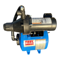
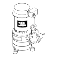
The Teel Deep Well Submersible Pump is designed for use in 4-inch (or larger) interior diameter wells in home, farm, and industrial deep well applications. These units come with the pump and motor completely assembled. For three-wire units, a control box must be ordered separately.

Function Description:

The pump's primary function is to draw water from deep wells for domestic water systems. It is not intended for use in swimming pools or for pumping flammable liquids such as gasoline, fuel oil, or kerosene. The pump operates by being submerged in the well, pushing water up through discharge piping to a pressure tank or directly into the water system.

Important Technical Specifications:

The pumps are available in various horsepower (HP) ratings, stages, and GPM (gallons per minute) capacities, with different voltage requirements (115V or 230V) and corresponding service factor amps.

  • HP Ratings: 1/3 HP, 1/2 HP, 3/4 HP, 1 HP, 1 1/2 HP.
  • Stages: Ranging from 4 to 22 stages, depending on the model and GPM capacity.
  • GPM Capacities: Available in 5 GPM, 10 GPM, and 20 GPM series.
  • Voltage: 115V or 230V, 60 Hz.
  • Discharge Opening: All models feature a 1 1/4" discharge opening.
  • Control Box: Required for 3-wire units (e.g., 4P840, 4P841, 4P843, 4P844, 4P845, 4P846). 2-wire units do not require a separate control box.
  • Discharge Material: Models 4RH01 thru 4RH06, 4RG76 thru 4RG84, 4RG94 thru 4RG97, and 4RG99 feature thermoplastic discharge. Models 4P847A thru 4P851A and 4P852 thru 4P856 feature cast iron discharge.
  • Winding Resistance (Ohms): Varies by model, HP, and voltage, typically measured at 68°F. For 3-wire motors, readings include Main (Blk-Yel), Start (Red-Yel), and Total (Blk-Red).
  • Load Current (Amps): Varies by model, HP, and voltage.
  • Fuses: Standard and Dual Element fuses are specified for each model.
  • Wire Size: Critical for proper operation, with charts provided for maximum distance in feet for various HP and voltage combinations, using AWG wire sizes #14 through #4. Using undersized wire can lead to low starting voltage, early pump failure, and void warranty.

Usage Features:

  • Installation: Requires careful adherence to the National Electrical Code (NEC) Article 250 for grounding to prevent electrical shock. The pump should be installed in a sand-free, straight well with sufficient water flow. Chlorination of the well before installation is recommended to prevent contamination.
  • Control Box: For 3-wire pumps, the motor and control box horsepower and voltage must match exactly. The control box contains wiring diagrams and instructions for proper connection.
  • Wiring: Electrical hookup should be performed by a qualified electrician. Power supply should be a separate circuit with adequate fusing and a disconnect box. Power cable must be protected from scratches, cuts, or abrasions and should not come into contact with oil, grease, hot surfaces, or chemicals.
  • Splicing: Underwater cable splices require butt connectors and plastic sleeves. Instructions emphasize making a watertight splice to prevent damage to motor windings or electrolytic deterioration.
  • Pressure Tank Systems: Can be installed with standard air volume control tanks or pre-charged tanks (fixed diaphragm or bladder type). Pre-charged tanks simplify piping and have fewer moving parts.
  • Safety: A pressure relief valve capable of passing full pump flow at 75 PSI must be installed between the pump and tank to prevent tank blowup. The system should not be allowed to freeze, as this can damage components and void the warranty. Disconnect electrical power before working on the motor, control box, or wiring.
  • Performance: Performance charts provide gallons per minute at various vertical depths to water for 5 GPM, 10 GPM, and 20 GPM series pumps, helping users select the appropriate pump and tank size based on well conditions and water requirements. Suggested tank sizes are provided to ensure approximately 2-minute cycles at 80 ft depth to water; shallower wells may require a larger tank.

Maintenance Features:

  • Pre-installation Check: Examine the pump for damage and ensure the check valve works properly. Verify electrical supply for correct fusing, wire size, transformer size, and adequate grounding.
  • Insulation and Continuity Test: This test should be performed after splicing and during a test run in a barrel of water, and again after installation in the well but before final electrical hookup. An ohmmeter is used to check for insulation breakdown. Readings of 20,000 ohms or less indicate insulation breakdown, while readings between 20,000 and 500,000 ohms suggest cable or splice damage.
  • Well Seal Check: Periodically check the well seal at the top of the well to prevent surface water contamination.
  • Electrical Control Inspection: A competent serviceman should check the electrical controls at three-year intervals for preventive maintenance.
  • Troubleshooting: A comprehensive chart helps diagnose common issues such as fuses blowing, motor running but delivering little or no water, or motor not starting. It provides possible causes (e.g., incorrect voltage, defective pressure switch, air-locked pump, low water level, worn pump) and corrective actions (e.g., checking wire size, replacing fuses, adjusting pressure switch, checking motor winding resistance).
  • Control Box Test Chart: Provides procedures for general inspection, ground (insulation resistance) tests, capacitor tests, and triac/coil tests (for solid-state switches) to diagnose control box malfunctions.
  • Motor Electrical Data: Includes winding resistance and load current specifications for various models, crucial for diagnosing motor issues.
  • Waterlogged Tank: If a pre-charged tank system is used, the air chamber should be checked annually, and the air pressure maintained at 2 PSI below the pump's cut-in pressure. A waterlogged tank can lead to frequent pump cycling and premature motor failure.

teel 4P847A Specifications

General IconGeneral
Brandteel
Model4P847A
CategoryWater Pump
LanguageEnglish

Related product manuals