Installation (Continued)
See control box owner’s manual and
inside of control box lid for complete
instructions. See Figures 16B and 16C.
NOTE: Always follow electrical and
sanitation codes that apply!
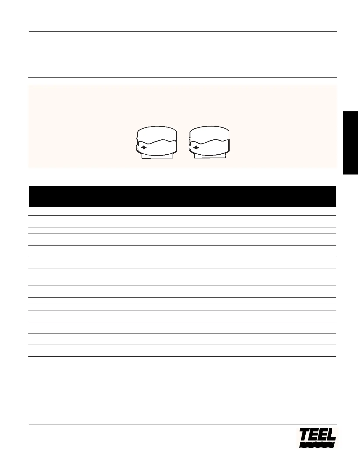
9. The Precharged Tank System uses a
flexible diaphragm or bladder to
separate the air and water in the
tank. The air chamber is pre-
charged through a tire valve on the
tank to a pressure 2 PSI below the
cut-in pressure of the pump.
Because the air is not in contact
with the water, it is not normally
absorbed by the water (See Figure
17). With this type of pressure
system, no air introduction or air
volume control fittings are needed
and the piping in the well is
simplified. The precharged tank
system has fewer moving parts,
simpler installation, and is the more
reliable of the two systems. Check
pre-charge annually.
As a precharged tank will deliver
more water between cycles
Models 4P847A thru 4P851A, 4P852 thru 4P865, 4RH01 thru 4RH06,
4RG76 thru 4RG84, 4RG94 thru 4RG97 and 4RG99
11
Teel Operating Instructions and Parts Manual
®
E
N
G
L
I
S
H
Figure 17
Motor Electrical Data
3-Wire
4P847A 115 1/3 1.4-1.8 6.5-7.9 7.9-9.7 9.2 9.2 0 25 10
4P852
4P855 115 1/2 1.0-1.3 4.1-5.1 5.1-6.4 12.0 12.0 0 30 15
4P848A 230 1/3 6.0-7.4 26.1-32 32.1-39.4 4.6 4.6 0 15 5
4P853
4P849A, 4RG99 230 1/2 4.2-5.2 16.7-20.5 20.9-25.7 6.0 6.0 0 15 7
4P856, 4RG76
4P851A, 4RH01 230 3/4 3.0-3.6 11.0-13.4 14.0-17.0 8.0 8.0 0 20 9
4P859, 4RG77
4P861, 4RG78 230 1 2.2-2.7 10.1-12.3 12.3-15.0 9.8 9.8 0 25 12
4P863, 4RG94
4RH02
4P862, 4RG79 230 1
1
⁄2 1.5-2.3 6.2-12.0 7.7-14.3 11.5 11.0 1.3 30 15
4P865, 4RG95
2-Wire Blk-Blk
4P854 230 1/3 7.0-7.4 – – – 4.6 – 15 5
4P857, 4RG80 115 1/2 1.0-1.3 – – – 12.0 – 30 15
4RH03
4P850A, 4RH04 230 1/2 4.2-5.2 – – – 6.0 – 15 7
4P858, 4RG81
4P860, 4RG82 230 3/4 3.0-3.6 – – – 8.0 – 20 9
4RH05
4P864, 4RG96 230 1 2.2-2.9 – – – 9.8 – 25 12
4RG83, 4RH06
4RG84, 4RG97 230 1
1
⁄2 1.5-1.9 – – – 13.1 – 35 15
Winding Resistance (Ohms) Load Current Dual
Main Start Total (Amps) Standard Element
Model Volts HP Blk-Yel Red-Yel Blk-Red Yellow Black Red Fuse Fuse
NOTES
1. Resistance varies + or -5% depending on temperature without drop cable. Above readings are correct at 68° F.
2. For motor PLUS drop cable, add resistance in Drop Cable Resistance Chart (See Figure 18). Current given in AMPS for
normally running motor. On single phase motors, Red-to-Yellow plus Black-to-Yellow = Red-to-Black reading.
3. Amp readings may vary ±5% at rated voltage.
4. For rated voltage of 115V, voltage must be between 105V and 125V. For rated voltage of 230V, voltage must be between
210V and 250V.
5. Electrical data for 3-wire motors based on capacitor start - capacitor run control boxes; cap start-induction run values will
differ.