Preinstallation (Continued)
c. Blown fuses.
d. High amperage draw (excess
current) resulting in tripping the
overload protector.
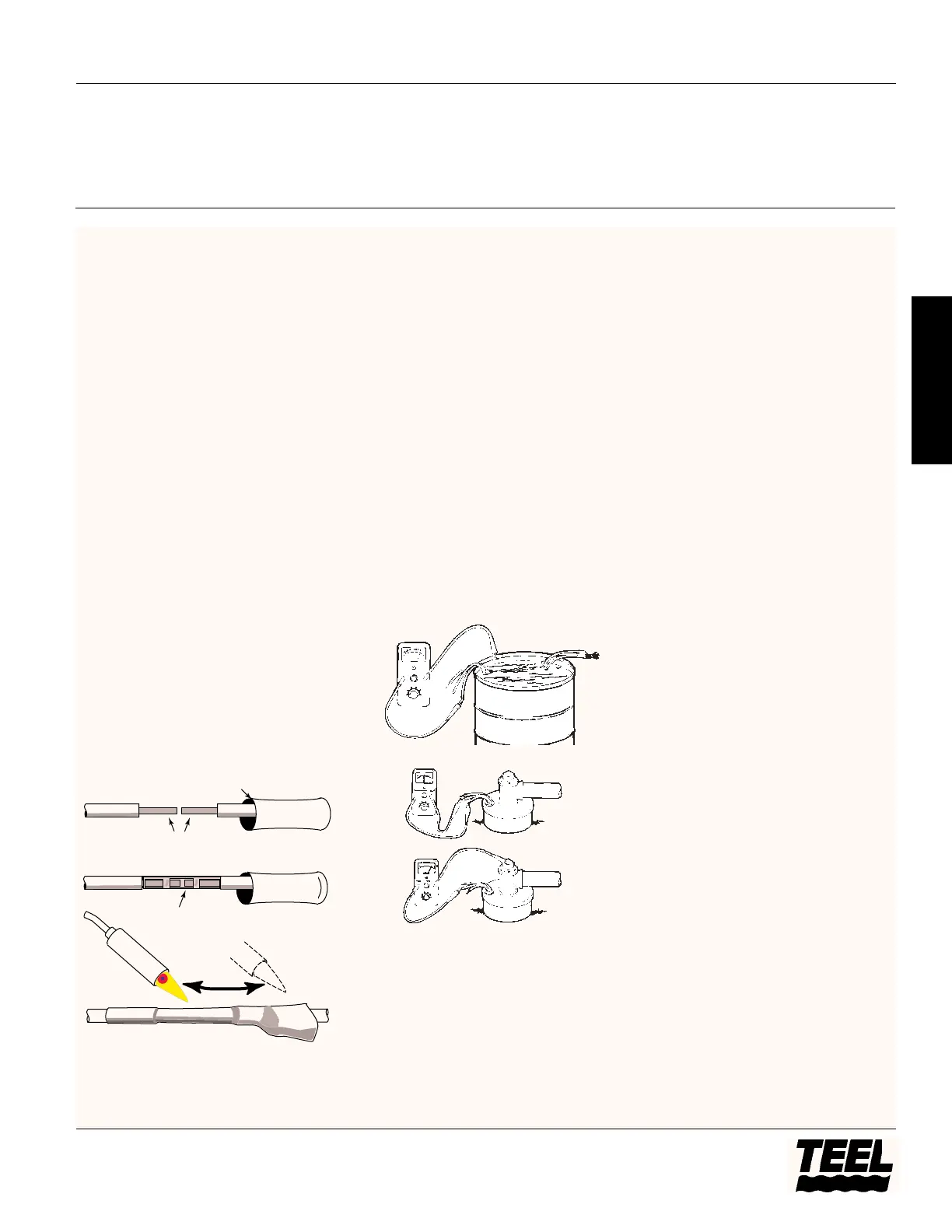
HEAT SHRINK SPLICING
FOR #8 WIRE CABLE
(Splice to #10 or smaller wire only)
(See Figure 2)
NOTE: When splicing to larger wires,
purchase splice kit to fit and follow
splice manufacturer’s instructions.
1. Remove 3/8” insulation from end of
motor pigtail leads and from drop
cable leads.
2. Place heat shrink tubing over
motor pigtail leads.
3. Insert leads into butt connector and
crimp with crimping tool. Pull leads
to check connection.
4. Center tubing over butt connector
and apply heat with a propane
torch (a match or lighter will not
supply enough heat).
NOTE: Keep torch moving; too much
concentrated heat in one place will
ruin tubing and may damage wires.
5. When tubing begins to shrink,
increase concentration of heat at
center of tube. As center of tube
collapses on wire, work heat out to
each end until entire tube is
collapsed tight around wire.
6. When splicing is complete, check
pump for continuous wiring
connections by running it in a
barrel of water. Insulation check
with ohm meter should be made at
this time. SEE INSULATION AND
CONTINUITY TEST.
INSULATION AND CONTINUITY TEST
Do this test after splicing is complete
and pump is being test run in a tank of
water. Repeat test after installation in
well but before final electrical hookup
is made to control box or pressure
switch (See Figures 3 and 4).
1. Zero the ohmmeter by clipping the
leads together and adjusting the
zero ohm knob until the needle
indicates zero. Zero the ohmmeter
before each use or every time
selector switch is changed.
2. Clip one ohmmeter lead to bare
cable end.
3. Clip the other lead to edge of steel
tank in which pump and cable are
submerged. If pump is already in
the well, clip lead to metal
discharge pipe, metal well casing,
or motor ground lead.
4. A reading of 20,000 ohms or less
indicates a breakdown in the
insulation; in this case pull the
pump. If reading is between 20,000
and 500,000 ohms, cable or splice is
damaged; lift pump and slowly
raise cable from water (DO NOT try
to use the cable to take the weight
of the pump) with ohmmeter still
connected. When trouble spot
moves clear of the water,
ohmmeter needle will swing
toward ∞.
Installation
Install pump in a well which is sand
free, straight, and has sufficient flow
of water to supply the pump. Clear
well of sand and any other foreign
matter with a test pump before
installing your new submersible pump.
NOTE: Using the submersible pump to
clean the well will void the warranty.
When drilling a new well in an area
where sand is a problem, a sand screen
should be installed to protect the
pumping unit.
IMPORTANT: You will need the
following tools and fittings to properly
install your submersible pump.
• Pipe Wrenches
• Pipe vises or clamps
• Tripod
• Chain hoist or block and tackle
• Fittings
• Enough cable
• Tape or clamps to fasten cable
to discharge pipe
• Discharge pipe on convenient
lengths
• Well seal
• Fused disconnect switch
Models 4P847A thru 4P851A, 4P852 thru 4P865, 4RH01 thru 4RH06,
4RG76 thru 4RG84, 4RG94 thru 4RG97 and 4RG99
5
Teel Operating Instructions and Parts Manual
®
E
N
G
L
I
S
H
1. Keep the heat moving.
2. Don't overheat.
 Loading...