Electrical Installation
Hazardous voltage.
Disconnect power
before working on pump, motor,
pressure switch, or wiring.
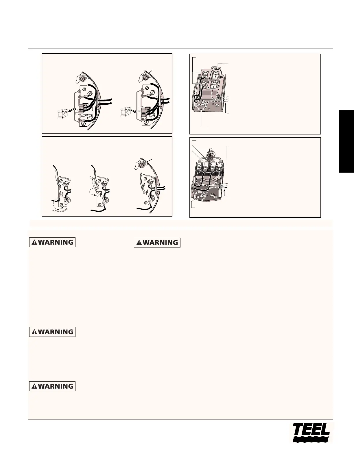
Your Motor Terminal Board (under the
motor end cover) and Pressure Switch
look like one of those shown above.
Convert to 115 Volts as shown. Do not
change motor wiring if line voltage is
230 Volts or if you have a single
voltage motor. Connect power supply
as shown for your type of switch and
your supply voltage.
Hazardous voltage.
Can shock, burn, or
kill. Connect ground wire before
connecting power supply wires. Use the
wire size (including the ground wire)
specified in the wiring chart (Page 10). If
possible, connect the pump to a separate
branch circuit with no other appliances
on it.
Explosion hazard.
Do not ground to a
gas supply line.
WIRING CONNECTIONS
Fire hazard.
Incorrect voltage
can cause a fire or seriously damage the
motor and voids the warranty. The
supply voltage must be within ±10% of
the motor nameplate voltage.
NOTE: Dual-voltage motors are factory
wired for 230 volts. If necessary,
reconnect the motor for 115 volts, as
shown. Do not alter the wiring in
single voltage motors.
Install, ground, wire, and maintain
your pump in compliance with the
National Electrical Code (NEC) in the
U.S., or the Canadian Electrical Code
(CEC), as applicable, and with all local
codes and ordinances that apply.
Consult your local building inspector
for code information.
CONNECTION PROCEDURE
1. Connect the ground wire first as
shown in Figure 6. The ground wire
must be a solid copper wire at least
as large as the power supply wires.
2. There must be a solid metal
connection between the pressure
switch and the motor for motor
grounding protection. If the
pressure switch is not connected to
the motor, connect the green
ground screw in the switch to the
green ground screw under the
motor end cover. Use a solid copper
wire at least as large as the power
supply wires.
3. Connect the ground wire to a
grounded lead in a service panel, to
a metal underground water pipe, to
a metal well casing at least ten feet
(3M) long, or to a ground electrode
provided by the power company or
the hydro authority.
4. Connect the power supply wires to
the pressure switch as shown in
Figure 6.
You have just completed the wiring
for your pump.
Please go to Page 10 for startup
preparations.
Models 3P740A, 4P037, 4P038, 4P039 and 4RJ96A
9
Teel Operating Instructions and Parts Manual
E
N
G
L
I
S
H
Figure 6 – Motor wiring connections through Pressure Switch. Match motor voltage to line voltage.
1.
1.
2.
2.
3.
3.
1.
1.
2.
2.
 Loading...