Spreader Arms
front rear
U.S. and foreign patents apply. Other foreign patents pending.
ASSEMBLY INSTRUCTIONS
F5000
TM
&
F6000
TM
(L)
(R)
DO NOT DISCARD - KEEP FOR FUTURE REFERENCE.
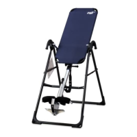
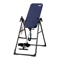
STEP ONE
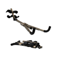
Assemble the A-frame Base (F51002)
• Open the A-frame and make sure that the spreader arms are locked flat.
(See Figure 1)
Figure 1
ITEMS FOR ASSEMBLY ITEM #’s
A-frame base F51002
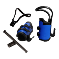
Main shaft w/ front ankle clamp F51039
Table frame with mat F51021
(F5000)
F61021 (F6000)
Hand grips (2) and F51069
1/2”
(13mm) hex bolts (6) H11202
Two (2) roller hinges F51064
Two (2) wrenches F51088
Rear bar with ankle clamps F51052
2”
(51mm) Hex Bolt / Nut / Washer F51087
Black Rubber Plug F51056
Triangle-head knob F51063
Foot platform F51060
F51002
F51039
F51021 (F5000)
F61021 (F6000)
Bolts may be
packaged
separately or
assembled in
hand grips.
H11202
F51069
F51064
F51088
F51087
F51052
F51060
F51056
F51063
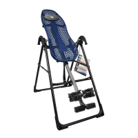
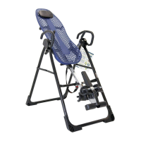
STEP TWO
Install Hand Grips (F51069) on A-frame Base (F51002)
• Place one of each hand grip (left / right) over the outside edge of the corre-
sponding hinge plate. (See Figure 2)
• Insert three 1/2” (13 mm) hex bolts (H11202) through the hinge plate into each
hand grip. Use the wrenches provided to tighten the bolts, being careful not to
over tighten.
Carefully remove the individual parts from the carton. You should have all of the items listed below. If any items are missing or damaged, contact
your retailer or customer service directly (See Pg. 4).
Before you begin: These instructions will guide you in properly assembling the unit. Please review all the steps before beginning assembly.
Carefully adhere to the Assembly Instructions and Owner’s Manual to help ensure user safety and product integrity.
NOTE: Bolts may be
packaged separately
or assembled in
hand grips.
Figure 2
PRE-ASSEMBLY
1. It is your responsibility to familiarize yourself with the proper use of the equipment and the inherent risks of inversion, such as falling on your
head or neck, pinching, entrapment or equipment failure.
2. This product is not designed for persons over 6’6” (198 cm) or 300 lbs (136 kg). Structural failure could occur or head/neck may impact floor
during inversion. Serious injury or death could result.
3. DO NOT use the equipment without a licensed physician’s approval and a review of the medical contraindications, as noted in the Owner’s Manual.
4. Failure to assemble and/or use the equipment as directed may void the manufacturer’s warranty on this product and could result in injury or death.
5. DO NOT use the inversion table until you have thoroughly and carefully read the Owner’s Manual, viewed the Instructional Video, reviewed all
other accompanying documents, and inspected the equipment.
6. The steps in the video directly coincide with the steps detailed in these Assembly Instructions.
7. Choose a level surface for assembling and operating the table.
8. Follow each step in sequence. Do not skip ahead.
9. Make sure that all fasteners are secure.
10. PRIOR TO USE, test and inspect the table. Make sure the table rotates smoothly to inverted position and back.
!
WARNING
ASSEMBLY