System Installation
NC356CE Module: This device is entirely configured through the LS450 Config Tool software. The
NC356CE enables legacy stations to function on the Tek-CARENetwork.
Things to consider when updating to an NC356CE from an NC351A:
l Go over existing "as-built" wiring plans to review where wiring will need to be upgraded. If exist-
ing wiring plans cannot be found, a site survey must be done to configure the current wiring topo-
logy.
l Keep in mind the NC356CE can only hold 64 stations per CE, with addresses of 0-31 per station
port. Any original station addresses above 31 needs to be revised to fit the addressing scheme for
the station port on the NC356CE.
l If updating the system from a PM456 to an NC356CE, the existing CT318RT connector will not
fit on the NC356CE. The CT318 included with the NC356CE will fit the module perfectly.
However, the header on the CT318 may be swapped with the CT318RT right angle connector
header to avoid rewiring.
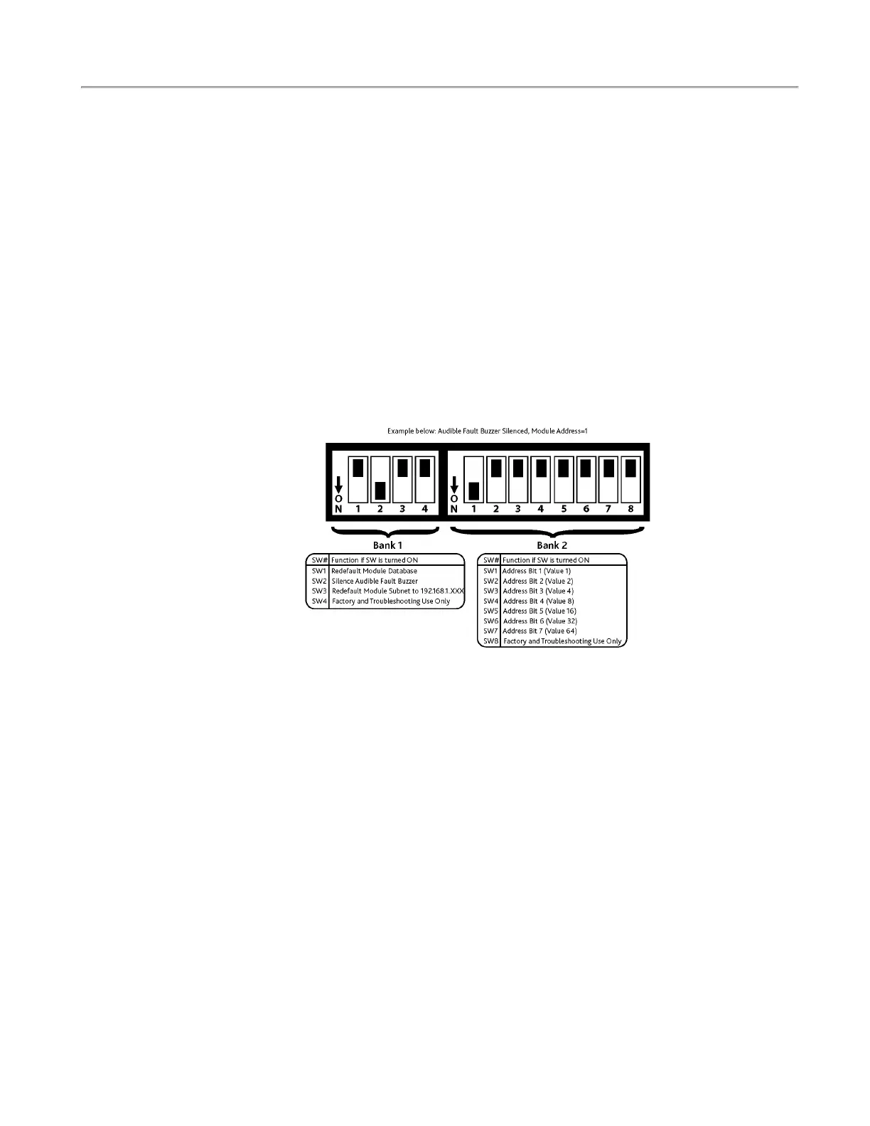
On the front of the NC356CE Module, you will find a bank of dip switches. These dip switches are used
to configure various options on the CE module and to provide an address for the module itself. See the
dip switch diagram for the NC356CE below.
Figure 9 - Gen2 Tek-CAREModule Dip Switch Diagram
IR3xx-series Stations: These devices are addressed by turning on and off the 7 available dip switches
located on each device. Stations that occupy the same port must all have unique addresses (ranging from
00 to 31). The 7-switch dip switch uses a binary configuration method (1 has a value of 1, 2 a value of
2, 3 a value of 4, 4 a value of 8, etc.). Using these values, the station address is represented by the sum
of the values of all switches that are turned on. For example, if switches 2 (value 2) and 5 (value 16) are
turned on, the address is 18 (2+16=18). Using this method, values of 00 to 31 can be generated using
only switches 1 through 6.
The four-digit Station ID is an amalgamation of the Module Address, the port the station is plugged
into, and the dipswitch address of the station. For example. if the module address is 3 and the station is
addressed 30 in the lower port 0, the station ID would be 0330. If the station is addressed as 1 in the
higher port 1, it would be 0332. The LS450 Config Tool software will display these station IDs on the
Stations page which should be edited to be architectural room names. See IL855 LS450 Config Tool
Manual for further details.
IR315 Duty Station: In addition to the dip switch address settings, the IR315 also has a tone control
adjustment (via three pin header) to set annunciation tone levels.
SF380 Single Patient Station: Refer to Figure 29 on page 44 for dip switch settings. NOTE: SF380 sta-
tions must be programmed for Personal Attn. Priority Level.
SF381 Standalone Bath Station/SF382 Standalone Code Station: Refer to Figure 31 on page 46 for
dip switch and jumper (shunt) settings.
16|IL1057 Tek-CARE300III Installation Manual
Copyright
©
TekTone Sound and Signal Mfg., Inc. All Rights Reserved