Patient Station Ports: Each patient station port supports up to 32 patient stations and a maximum of
1000′ feet of interconnecting cable. This maximum distance does not include peripheral wiring con-
nections, and only reflects the common wiring between all of the stations on that particular port and
their associated connection to the NC356CE. The following must be observed for patient station wiring:
l Do not run cables to the bottom of the patient station back boxes, because there is no access for
cable passage.
l At all splice points, the common cable shields must be kept isolated from all other circuits and
fed through as any other conductor would be. The shields must be continuous through the entire
run and must be isolated and taped back at the end of the run. When connecting the common
cable to the central equipment, the shields will be connected to the shields of the interconnecting
wire harness, CT318 (also known as “whip” or “pigtail” connector).
l Each patient station port has one audio path. If a system is known to have a small quantity of sta-
tions that will occupy only one or two ports, the installer should consider redistributing the
devices evenly among all of the available station ports. This enables all of the available audio
paths for use in system operation, allowing two simultaneous paths, and increasing call response
efficiency.
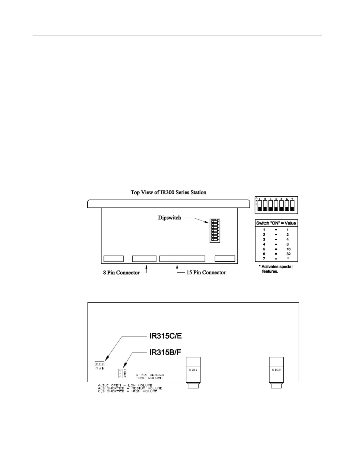
Figure 7 - IR3xx-series Stations Dip Switch Location and Switch Values
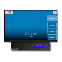
Figure 8 - IR315-series Duty Station Layout
Copyright
©
TekTone Sound and Signal Mfg., Inc. All Rights Reserved
IL1057 Tek-CARE300III Installation Manual | 15
System Installation