System Installation
Audio Adjustments
Adjustments can be made to change or improve the volume and quality of the audio on the Tek-
CARE300III system. There are basically three adjustments that can be made by installers to affect the
audio of the system. Speaker volume and microphone gains can be adjusted for each station using the
LS450 Config Tool software, and there is an audio trim pot for each audio bus port.
The audio bus of the Tek-CARE300III is susceptible to electronic noise induced by other building sys-
tems. Most of this noise can be removed by use of the trim pots on each audio bus port. In order to reach
the trim pots, a very small flathead screwdriver (1/16" blade) is required.
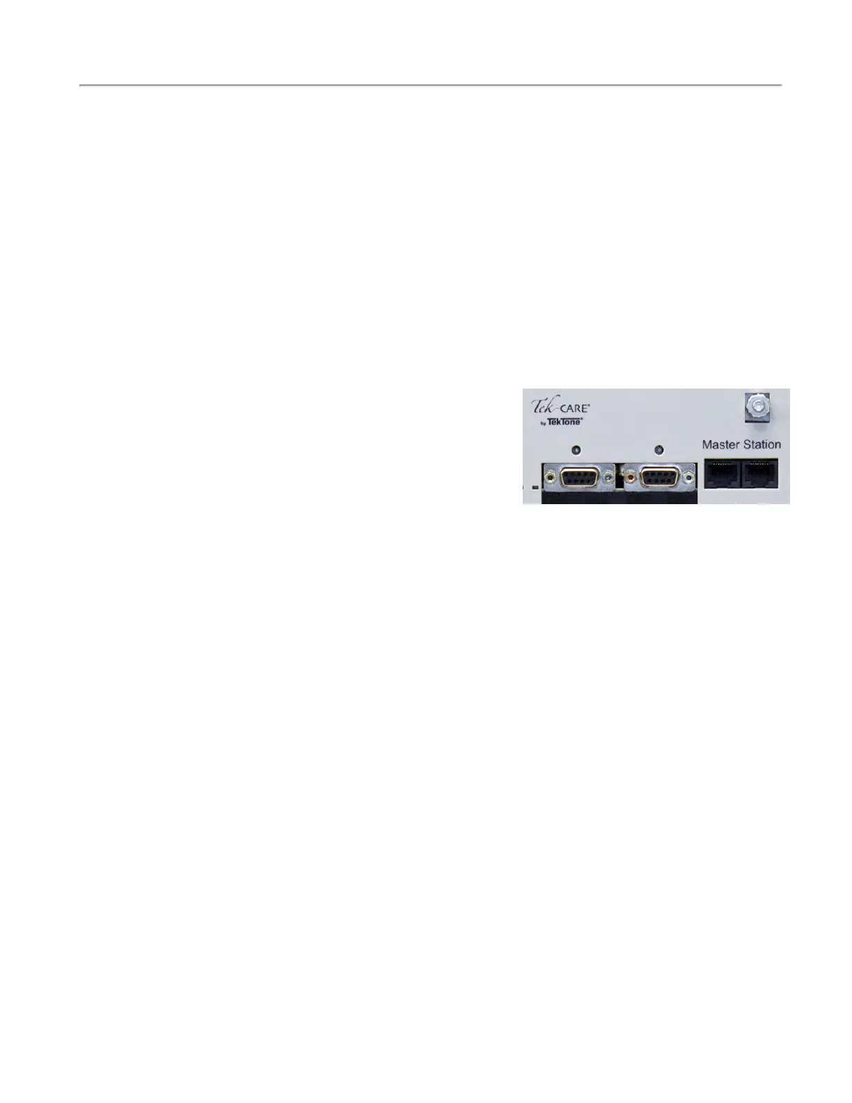
1. Connect an NC415AV or NC404TS Master Station directly to the NC356CE module using a
short patch cable. You must be able to reach both the NC356CE module and the
NC415AV/NC404TS Master Station at the same time during this procedure.
2. Dial a Station ID that is connected to Port 0 from the master station, and establish an audio con-
nection using the Talk button, not the handset, of the master station.
3. Release the TALK button. You should now have an open audio channel, and be listening to the
station you dialed through the speaker on the connected master station.
4. Using a flathead screwdriver, turn the potentiometer
for Port 0 approximately 12 turns clockwise. This
ensures that the potentiometer is maxed out. Note
that the potentiometer will not stop at the end of its
travel, but will spin freely. This is normal.
5. With the potentiometer fully clockwise, you may
hear a considerable amount of background and data
noise on the open audio channel. This is normal.
6. Begin turning the potentiometer counterclockwise. After six full rotations, the potentiometer will
be in the center of its travel.
7. Make small clockwise and counterclockwise adjustments to the potentiometer while listening to
the audio connection. Too far clockwise or counterclockwise will induce noise on the audio bus.
8. Adjust the potentiometer so that the noise level on the channel is as low as possible. Remove
your screwdriver from the potentiometer and clear the audio connection.
Finally, dial a Station ID that is connected to Port 1 from the master station. Repeat the process outlined
above while adjusting the audio trim potentiometer for Port 1 of the NC356CE module.
Below is the wiring specifications for the interconnecting cable for the patient stations.
Data Wires:
#18 AWG, 1 twisted pair (8 twists per ft.) plus 1 conductor (3 conductors, 7
str. BC) with 100% aluminum/mylar shield and #20 AWG TC drain wire. Nom-
inal insulation 0.017", nominal OD 0.245" and capacitance <24pF/ft. Recom-
mended conductor colors are ORANGE, YELLOW and GREEN. Overall
jacket.
Power Wires:
#18 AWG, 3 conductors (7 str. BC) with 100% aluminum/mylar shield and
#20 AWG TC drain wire. Nominal insulation 0.009" and nominal OD 0.175".
Recommended conductor colors are BROWN, RED and BLUE. Overall jacket.
Audio Wires:
#18 AWG, 1 twisted pair (8 twists per foot, 2 conductors, 7 str. BC) with
100% aluminum/mylar #20 AWG TC drain wire. Nominal insulation 0.017",
nominal OD 0.235" and capacitance <24 pF/ft. Recommended conductor colors
are VIOLET and GRAY. Overall jacket.
Ground Wires:
#16 AWG, 1 conductor (26 str. BC) with nominal OD 0.101". Recommended
color is BLACK.
14|IL1057 Tek-CARE300III Installation Manual
Copyright
©
TekTone Sound and Signal Mfg., Inc. All Rights Reserved