System Installation
IR3xx-series Stations—General Information: All of the IR3xx-series devices’ electronics are mounted
on a flame-retardant ABS plastic panel. Users must observe ESD precautions [see A Word about ESD
(Electrostatic Discharge) on page 4] when handling these devices as they may be damaged if improp-
erly handled. Each of the IR3xx-series stations require a unique address, which is set using the on-board
dip switch. Plug-on connectors are provided for easy installation. The IR300-series must be located cent-
ral to the various peripheral devices that are connected to it. See IR3xx-series Station—General Inform-
ation on page 9 for additional details.
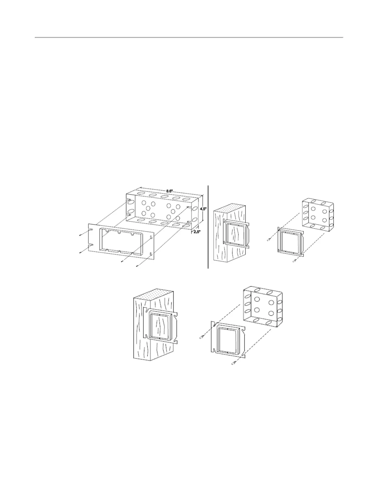
The IR3xx-series stations use the Steel City H3BD back box with a 3GC plaster ring. Refer to Figure 1
below for mounting. The minimum dimensions for the back box must be not less than 8.6" × 4.5" × 2.5",
and the minimum clearance from current carrying parts to dead metal parts must be no less than 0.5". If a
station has a pillow speaker module, a bigger back box is recommended. These devices are typically loc-
ated for convenience, most commonly at the head of the patient’s bed, unless specified otherwise. The
IR3xx-series stations must be located within 1000′ feet of the NC356CE, and so that furniture, curtains
and other features do not interfere with audio communication. See the wiring diagrams at the end of this
manual for additional requirements. NOTE: There are additional guidelines for station location in the
wiring installation section. The operating environment for the IR3xx-series stations is 10–40°C with rel-
ative humidity not exceeding 80%. See the Wiring Installation on page 12 for additional information.
Figure 1 - Mounting IR-series Stations Figure 2 - Mounting LI380, LI386 Dome/Zone
Lights
Figure 3 - Mounting SF-series Stations
IR300 Multipurpose Station: The IR300 Multipurpose Station serves as an address point for stand-alone
peripheral device applications. It has no external controls, but does have additional control connections
brought out to an additional header (refer to Figure 28 on page 43). Activate a special feature on the
IR300 station (only) by turning on dip switch 7 to allow the device to operate its dome lamp outputs as
zone lamps for zone annunciation.
8|IL1057 Tek-CARE300III Installation Manual
Copyright
©
TekTone Sound and Signal Mfg., Inc. All Rights Reserved