Theory of Operation—2213 Service
the X-Y Mode, XY Switch transistor Q720 is biased on to
provide a ground reference at the other input of the dif
ferential amplifier (at the base of Q731). The output of
the differential amplifier, taken from the collector of Q731,
is amplified by Q736.
A feedback network connected between the output of
Q736 and the base of Q730 provides the circuitry required
for the X10 magnification feature. In the unmagnified
mode, X I0 Magnifier switch S734 is closed and the feed
back is provided by the paralleled combination of R732
and C732. Resistor R732 sets the unmagnified amplifier
gain and C732 provides the HF compensation.
When the X10 Magnifier push button is pressed in,
S734 opens and additional components are added to the
feedback network. With the feedback reduced, the
amplifier gain is increased by a factor of 10. The X10 Gain
potentiometer (R733) is adjusted to produce the exact gain
required. High-speed linearity compensation of the feed
back network is provided by adjustable capacitor C734.
XY Amplifier
When the X-Y display mode is selected using the SEC/
DIV switch, the XY signal line goes LO and XY Switch
transistor Q720 is biased off. The XY signal is also applied
to FET Q714 (used as a switch to prevent crosstalk) in the
XY Amplifier to bias it on. With this action, the XY
Amplifier is enabled to pass X-Axis signals on to the
Horizontal Preamplifier. Another function of the XY signal
is to disable the Sweep Generator to prevent the Sweep
signal from being applied to the Horizontal Preamplifier.
The X-Axis signal is derived from the Channel 1 internal
trigger signal and applied to the base of Q703. Transistor
TO CRT
HORIZONTAL
DEFLECTION
PLATES
3827-17
@
3-21
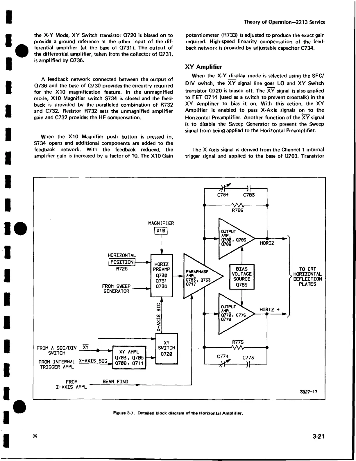
Figure 3-7. Detailed block diagram of the Horizontal Amplifier.
 Loading...


