SECTION 8
DIAGRAMS
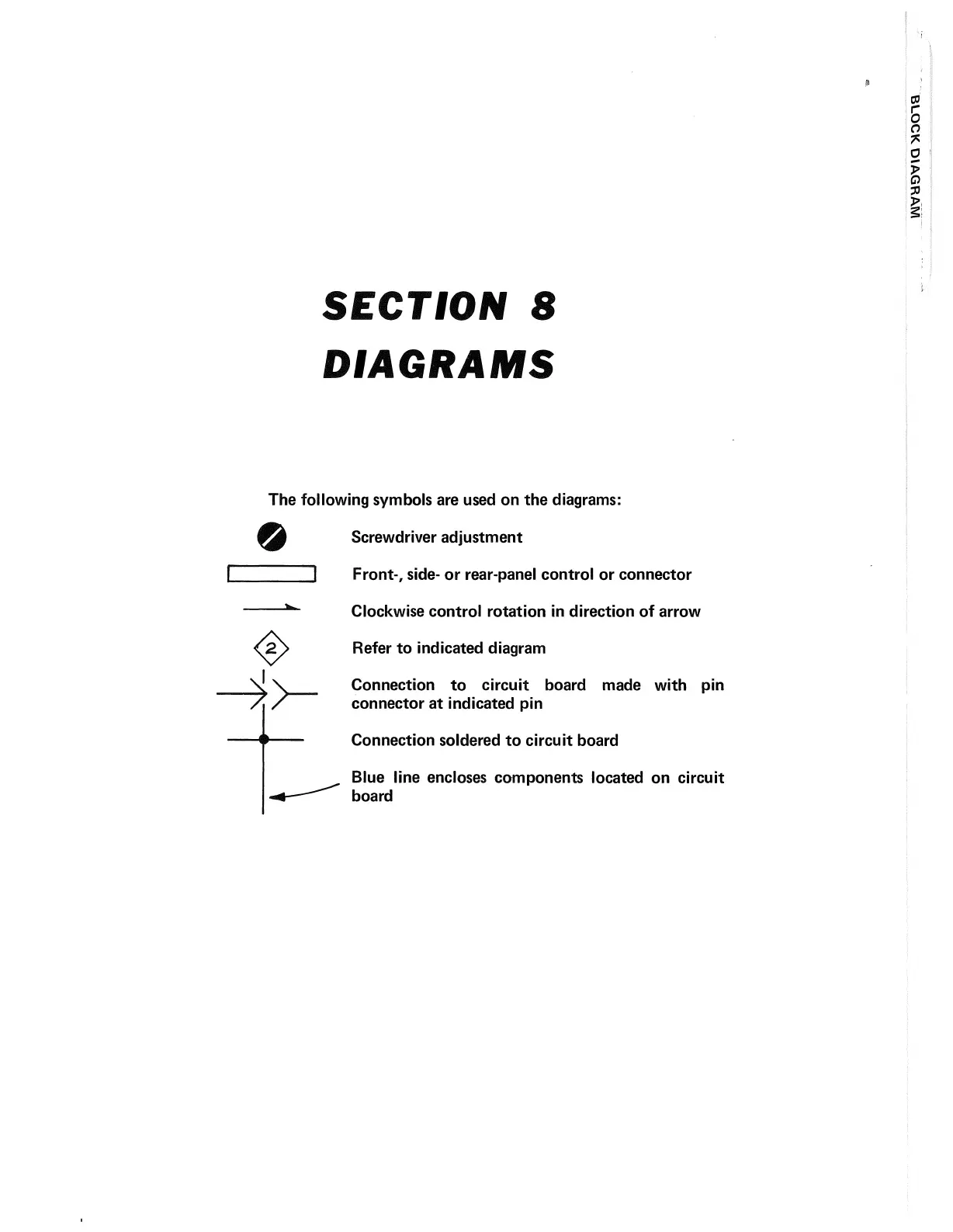
The following symbols are used on the diagrams:
Screwdriver adjustment
I Front-, side- or rear-panel control or connector
------
w Clockwise control rotation in direction of arrow
<5>
Refer to indicated diagram
Connection to circuit board made with pin
connector at indicated pin
Connection soldered to circuit board
Blue line encloses components located on circuit
board