calibrate the dispersion to specifications, the fol-
lowing techniques may be tried.
Shift the sweep oscillator RF output voltage to a
new level.
(The output voltage level must remain
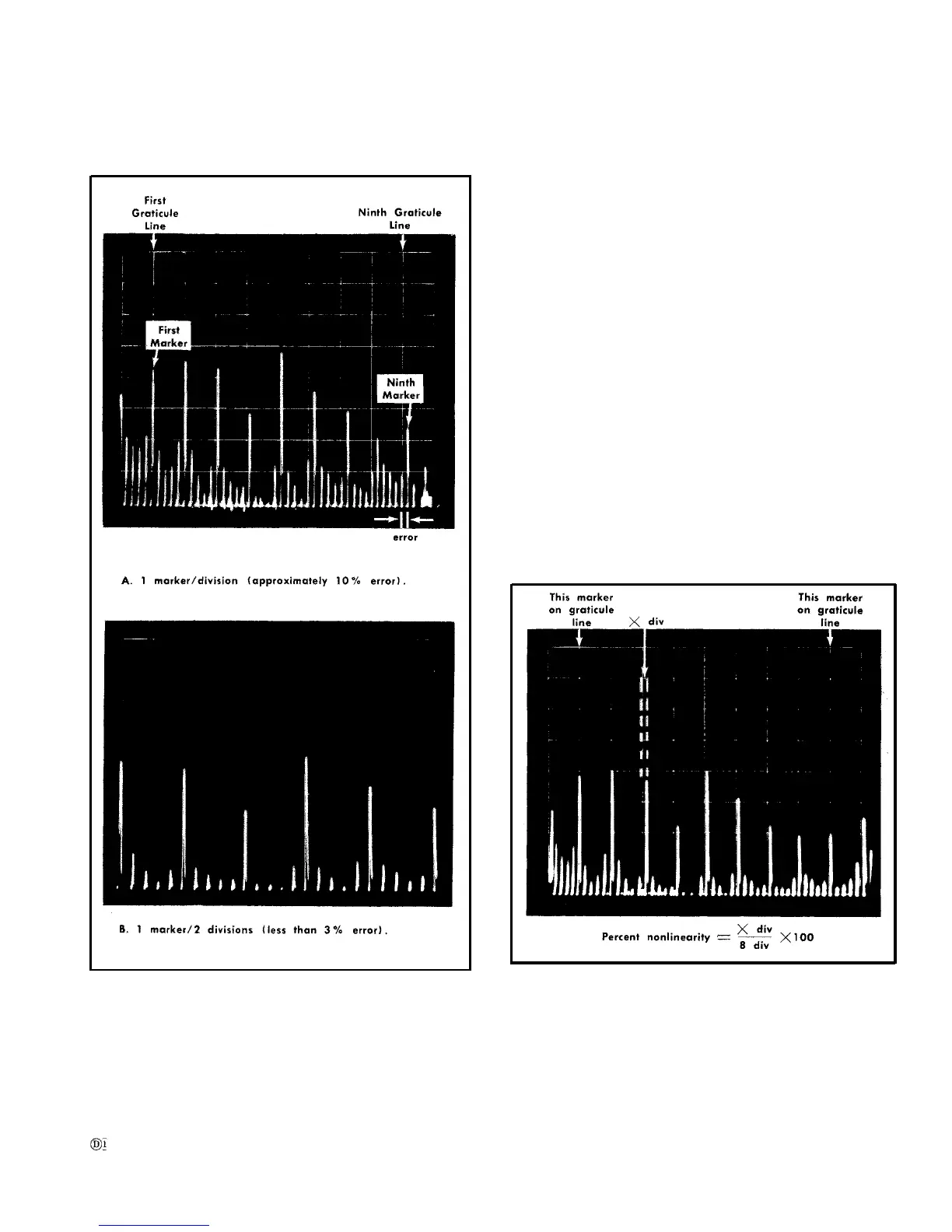
Fig. 6-20, Measuring dispersion accuracy.
within
0.75 to 1.0 volt). If the level is changed,
the Center Freq Range adjustment and a check for
sidebands must be repeated.
Interchange Q310, Q340 and Q350. The slight
differences between the transistor parameters will
have some effect on display linearity. Changing
these transistors is only recommended if new tran-
sistors have been installed or components have
been changed and linearity cannot be obtained
by other means,
a. Equipment setup is given in Fig. 6-19.
b. Apply .1 µs and 10 ns markers from the Time-Mark
Generator (Type 184) through a 20 dB attenuator to band
B RF INPUT connector, Set the VERTICAL DISPLAY switch
to LOG position.
c. Adjust the Type 491 GAIN control for a display ampli-
tude of approximately 6 divisions. See Fig. 6-20. Set the
SOURCE switch to LINE and adjust the LEVEL control
for
a triggered display.
NOTE
More than one set of 1 MHz markers may appear
on the display.
To avoid confusion, tune the RF
CENTER FREQUENCY and FINE FREQ controls to
align the tunable markers with the fixed (IF feed-
through markers).
Fig. 6-21. Measuring dispersion linearity.
6-21