INTENSITY
FOCUS and ASTIGMATISM
INTENSIFIER
SCALE ILLUM
POSITION (Horizontal and
Vertical)
TIME/DIV
VARIABLE
TRIGGER
SLOPE
LEVEL
SOURCE
DISPERSION RANGE
DISPERSION-COUPLED
RESOLUTION
IF ATTENUATOR dB
IF CENTER FREQ Controls
VIDEO FILTER
VERTICAL DISPLAY
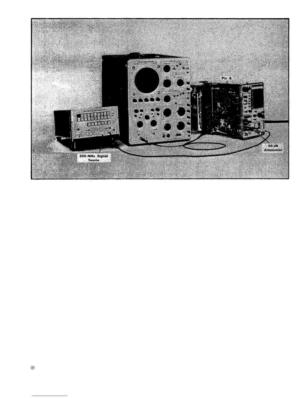
Fig. 6-23. Test equipment setup to adjust IF amplifier and the resolution bandwidth.
Type 491
GAIN
Midrange
Display of nominal
brightness
Adjusted for optimum
display definition.
OFF
As desired
Adjusted for a
horizontally centered
sweep on the graticule
baseline.
2 ms
CAL
+
Triggered sweep
LINE
kHz/DIV
Set the DISPERSION to
50, uncouple the RES-
OLUTION control and
turn fully clockwise.
All switches in off position
Midrange (000)
OFF
LIN
POWER ON
MIXER PEAKING
SEARCH
FINE RF CENTER FREQ Centered
PHASE LOCK Controls
INT REF FREQ
OFF
Test Oscilloscope
Time/Cm 1 ms
Volts/Cm
.05
Input Coupling
AC
Trigger LINE
23. Adjust IF Amplifier Response and
o
Resolution Bandwidth
a. Equipment setup is shown in Fig. 6-23.
NOTE
Resolution bandwidth should be pre-adjusted be-
fore calibrating the kHz/div dispersion. Repeat
this step after adjusting kHz/div dispersion if
kHz/div dispersion error is greater than 6%.
b. Apply 200 MHz signal (2nd harmonic of 10 ns) from the
Time-Mork Generator (Type 184) through a 20 dB attenuator
ond proper adapter to the RF INPUT connector.
Two alternate methods of 200 MHz signal application are
as follows:
6-23
 Loading...


