Fig. 6-24. Location of narrow band IF amplifier adjustments.
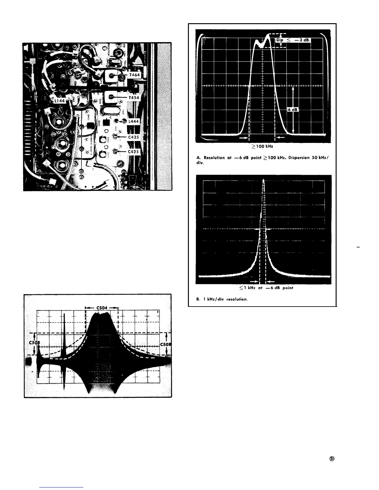
Fig. 6-26. Display pattern when resolution is correctly adjusted.
Fig. 6-25. Typical test oscilloscope display when C504 and C508
are adjusted correctly. Dispersion 50 kHz/div, RESOLUTION selector
fully clockwise.
1. Install the Waveguide Mixer Adapter into band C, RF
INPUT receptacle. Apply the 200 MHz signal from the Time-
Mark Generator through a 20 dB attenuator and adapter
to the Waveguide Mixer adapter. Switch the band selector
to c.
2. Apply 200 MHz signal below - 50 dBm from an ac-
curate signal generator through a 50
Ω termination or attenu-
ator and a P6041 or P6040 probe cable adapter to sub-
miniature connector J100 on the wide band-pass filter of the
honeycomb assembly.
c. Turn the GAIN central fully clockwise and switch in
the required IF ATTENTION to reduce the signal amplitude
to approximately 4 divisions.
6-24