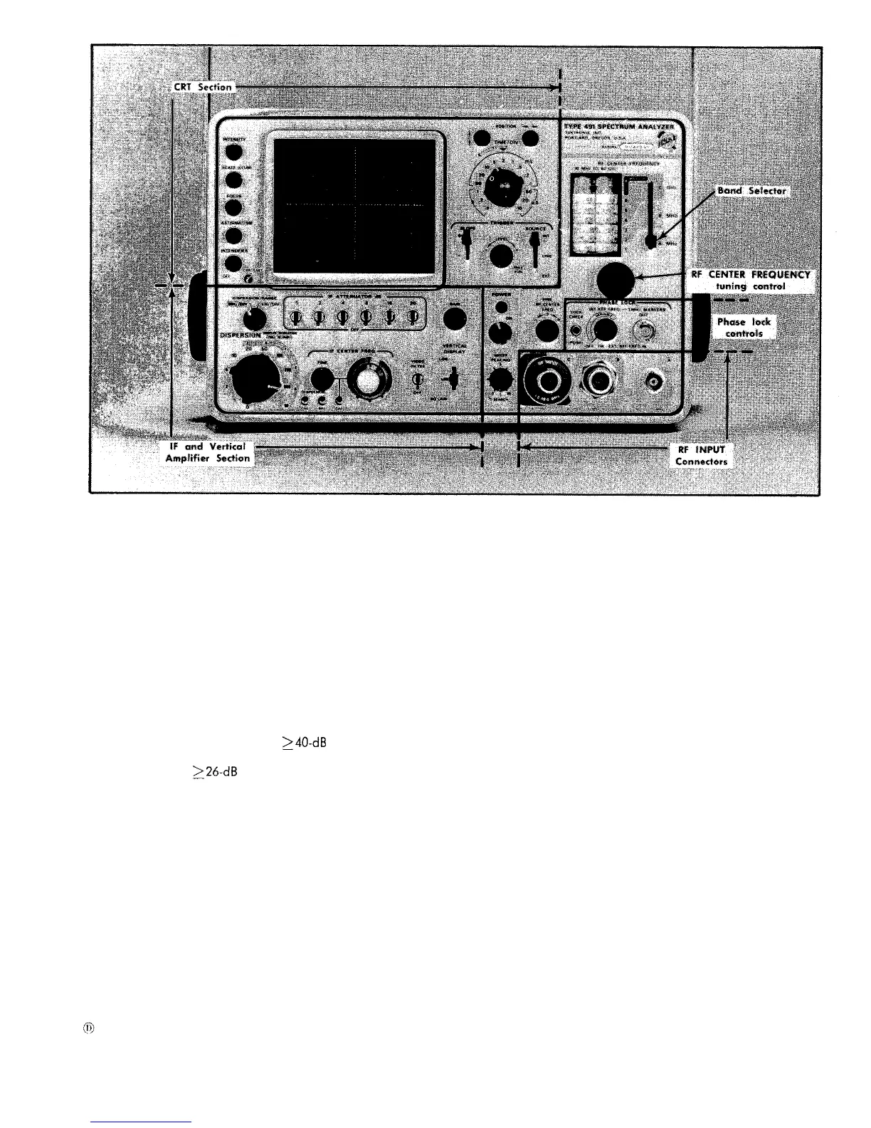
Fig. 2-4. Front panel controls and connectors.
FINE-A one turn control that operates in conjunction with
the IF control to provide a fine adjustment of the IF center
frequency.
CAL-With the IF CENTER FREQ control centered, it cali-
brates the IF center frequency to 200 MHz.
VIDEO FILTER-With the switch in the up position, the
video bandwidth is restricted, to reduce high frequency
video components such as noise, and reduce zero beats
when viewing signals near minimum resolution.
VERTICAL DISPLAY-Selects logarithmic, linear or square-
law display. In the LOG position, signal display amplitude
is a logarithmic function with a
³40-dB
dynamic range.
In the LIN position, signal display amplitude is a linear
function with a
³26-dB
range. In the SQ LAW position
signal display amplitude is a square law function and the
display is a function of signal power, The SQ LAW posi-
tion has a
≥13 dB dynamic range.
POWER-Turns power off and on to the Type 491.
INDICATOR LIGHT-indicates when POWER is applied to
the Type 491.
RF CENTER FREQUENCY-Tunes RF center frequency from
10 MHz to 40 GHz. With the IF CENTER FREQ control in
the 0 position, the RF CENTER FREQUENCY dial indicates
the center frequency of the display.
BAND SELECTOR-Switch selects RF Inputs and bands;
A (10-275 MHz), B (270-2000 MHz) and C (1.5-40 GHz).
FINE RF CENTER FREQ-A 10 turn control to provide a
fine adjustment of the RF local oscillator frequency.
Especially useful in tuning the oscillator to a phase lock
condition with the reference frequency.
MIXER PEAKING-A two position control that optimizes
the conversion of the first local oscillator for bands B and
C. Does not affect band A. In the SEARCH position the
mixer current is swept through a range by the sweep volt-
age. This insures an optimum mixer conversion or sensi-
tivity point within the dispersion range of the analyzer, so
all signals within a given dispersion pass through this opti-
mum sensitivity point as the signals are tuned across the
screen. The manual (0 to 10) position of the control pro-
vides an adjustment to optimize mixer conversion for any
fixed center frequency setting.
LOCK CHECK-A push button switch that applies the
phase lock output beat signal (between the local oscillator
and reference frequency) to the vertical display system.
Provides a visual indication to the operator of phase lock
operation.
INT REF FREQ-A switch and control. The control varies
the internal 1 MHz Reference Frequency over a range of
approximately 1 kHz. With the control in the OFF posi-
tion, the Internal Reference Frequency is turned off, and
an externally applied signal to the EXT REF FREQ IN
(1 MHz MARKERS OUT) connector becomes the reference
frequency.
2-5