1. Perform the necessary repairs. Replace all covers. All
d. Tighten the set screws.
screws must be tight.
7. Check the dial tape tracking on band B at several
2. Switch the band selector switch to B.
points, including each end of the band. The oscillator fre-
quency must track within ±1% of the dial frequency +200
3. Push the LOCK CHECK button and adjust the Type 491
MHz.
FINE RF CENTER FREQ control for a centered trace or +7.0
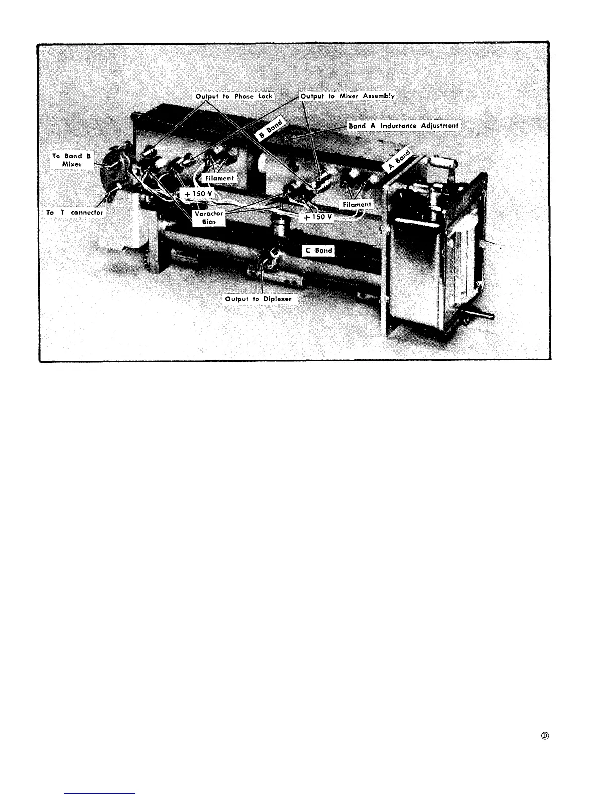
Fig. 6-47. Local oscillator assembly showing Voltage and signal connections.
6. Tune the band B oscillator to exactly 835 MHz. The
BAND A LOCAL OSCILLATOR
dial tape should read 635 ±8 MHz on scale 2. If the tape
does not read within this range, the coupling between the
two oscillators must be reset. Adjust the coupling as follows:
a. Loosen the two set screws through the flexible cou-
pling to the band B (rear) oscillator drive shaft.
b. Set the tape to read exactly 635.
c. Hold the front shaft at 635 on the dial and manually
tune the band B (rear) oscillator to 835 MHz.
CALIBRATION PROCEDURE
NOTE
This procedure is to be used only after replacing
V40 (the Band A local oscillator tube) or perform-
ing some other internal repair on the Band A local
oscillator. This procedure requires that the band
B local oscillator be operating and tracking to the
dial tape.
6-46
 Loading...


