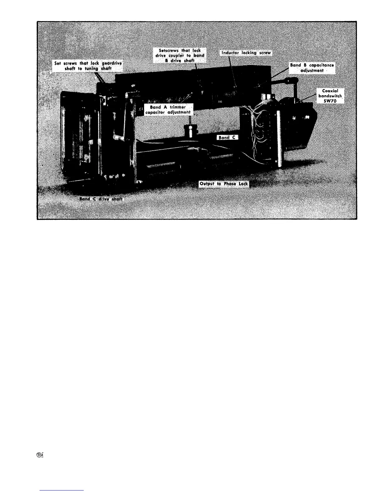
Fig. 6-49. Local oscillator assembly showing
volts at the varactor biers terminal for the band B oscillator.
See Fig. 6-48.
4. Use an accurate frequency meter to check the oscillator
frequency and tune the band B local oscillator to 835 MHz.
(Oscillator frequency can be checked by disconnecting the
Sealectro Connector J69 at the mixer output and connecting
the oscillator output through an adapter cable to the fre-
quency meter.)
5. Check the dial reading for 635 MHz on scale 2. If
dial is incorrect, loosen the set screws holding the coupling
between the drive shaft and the tuning shaft (see Fig. 6-48).
Tune the dial to read 635. This sets the dial tape to a known
frequency point on the tuning curve for both oscillators.
6. Check the dial tape tracking of the B band at several
points, including each end of the band. The oscillator fre-
quency must be within ± (1% of the dial tape frequency
plus 200 MHz).
7. Switch the band selector to A.
8. Push the LOCK CHECK button and adjust the FINE
RF CENTER FREQ control for a centered trace or +7.0 V at
the varactor bias terminal on band A local oscillator. See
Fig. 6-48.
9. Set the frequency meter to 210 MHz. Tune the dial to
10 MHz and adjust the A band inductance adjustment (Fig.
6-49] to tune the oscillator freuency to 210 MHz.
drive shaft coupling and tuning adjustments.
10. Set the frequency meter to 475 MHz. Tune the dial
tape to 275 and adjust the A band capacitance adjustment
(Fig. 6-49) to tune the oscillator frequency to 475 MHz.
11. Repeat steps 9 and 10 until both frequency check
points match the dial tape reading.
12. Set the frequency meter to indicate 375.5 MHz. Tune
the oscillator to 375.5 MHz. The frequency dial tape must
read between 174 and 177. If the tape does not read within
this range, both oscillators require special equipment to
calibrate and should be returned to Tektronix for repair and
calibration.
BAND B LOCAL OSCILLATOR
Calibration Procedure
This procedure requires that the band A local oscil-
lator be operating and tracking correctly. Both
band A and B covers must be in place and all
screws must be tight.
1. Set the band selector to band B. Push the LOCK CHECK
button and adjust the RF FINE FREQ control for a centered
display, or a varactor bias reading of 7.0 volts for band B
oscillator.
2. By means of a frequency meter or frequency counter,
set band B oscillator to 470 MHz. Note which side of 270
on scale 2 the dial indicates.
6-47
 Loading...


