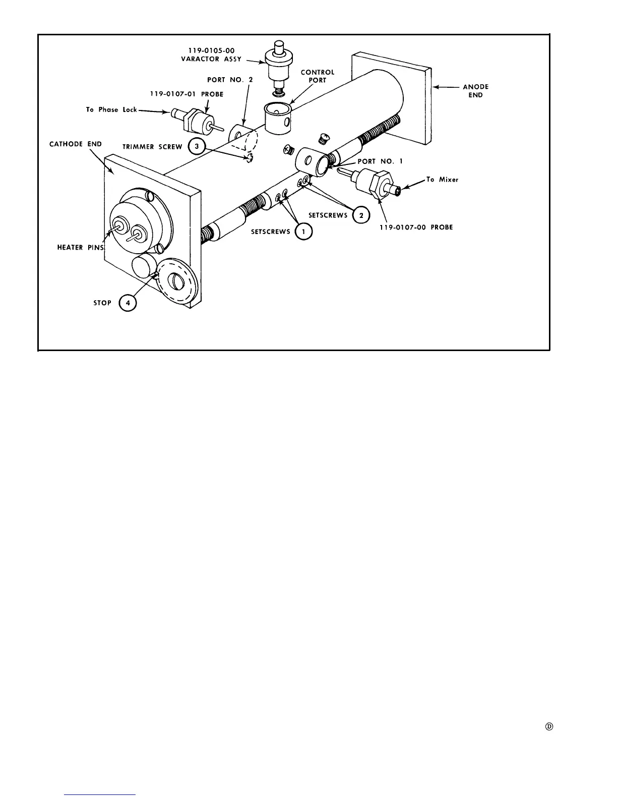
Fig. 6-49. Band C Assembly Alignment Diagram.
3. Turn the POWER switch to OFF. Loosen the inductor
10. Set the frequency meter to 835 MHz and tune the local
oscillator to this frequency. Check the dial reading. Must
read between 630 and 640 MHz.
If the dial does not read within this range, bath oscillators
require repair and adjustment using special equipment, The
assembly should be returned to Tektronix for repair and
calibration. See your local Tektronix Field Office or repre-
sentative.
lock screw on the left side of the oscillator chamber (see Fig.
6-48). This screws is on the left side slightly forward of the
center point. Do not confuse this adjustment with the high
frequency capacitor adjustment located between the two
spring-like wires protruding from the side wall.
4. If the dial reading in step 2 was above 270, more
inductance is required. Turn the inductor adjustment counter-
clockwise. If the dial reading was below 270, turn the
adjustment clockwise. Turn the adjustment approximately
one turn at a time then recheck.
5. Remove the screwdriver from the access hole, turn the
POWER switch ON and return the oscillator frequency to
470 MHz.
6. Again check the dial reading. If necessary again turn
off the POWER switch and repeat step 4 until the dial reads
270 when the oscillator frequency is 470 MHz.
7. Set the frequency meter to 1100 MHz and tune the dial
to 900.
8. Adjust the band B capacitance adjustment (see Fig.
6-48) to tune the oscillator frequency to 1100 MHz.
9. Repeat the inductance adjustment and capacitance
adjustment until the dial tracks at the low and high end of the
scale, then tighten the inductor lacking screw.
BAND C OSCILLATOR CALIBRATION
NOTE
This procedure should only be required after the
oscillator tube has been replaced. The oscillator
assembly must be removed from the instrument for
calibration. See Maintenance section.
Calibration of this oscillator is very critical and
should only be attempted by qualified personnel
with adequate facilities. The complete oscillator
assembly is listed in the Mechanical Parts list. We
recommend replacing the complete assembly and
returning the defective assembly to yaur Tektronix
Field office or representative.
Refer to Fig. 6-49 for the location of the sub-assemblies
and parts. The oscillator assembly must be removed for
6-48
 Loading...


