H— ill· It- β ill· Jl·* ll· AL· (^l· (^l· ll· I
c. Adjust the front panel AMPL CAL to its fully ccw posi
tion and set the Band 1 Gain R2031 (Fig. 3-42) on VR#2
fully ccw.
d. Disconnect P693 from the input to VR#1 module (Fig.
3-44) and apply a 10 MHz, -35 dBm signal from the signal
generator through a bnc-to-Sealectro adapter to J693. Ad
just the generator frequency to peak the signal.
e. Signal amplitude should be between 3.5 and 6.5 divi
sions. (If signal amplitude is not within these limits it indi
cates a gain problem in the VR.)
f. If the signal is above 5 divisions, adjust the Post VR
Gain R2038 (Fig. 3-42) for a 5 division signal amplitude (if
the signal amplitude is less than 5 divisions proceed to
part g).
g. Adjust the front panel AMPL CAL for a 7 division
signal.
h. Decrease the generator output to —45 dBm and
change the REF LEVEL to —40 dBm.
i. Adjust the 10 dB Gain R3035 (Fig. 3-44) of VR#1 so
' the signal amplitude is 7 divisions.
j. Change the generator output to —55 dBm and the
REF LEVEL to -50 dBm.
k. Adjust the 20 dB Gain R2023 (Fig. 3-44) for a 7 divi
sion signal amplitude.
I. Change the generator output to -7 5 dBm and the
REF LEVEL to -70 dBm.
m. Adjust the 10 dB Gain R2060 (Fig. 3-44) for a 7 divi
sion signal amplitude.
n. Increase the REF LEVEL to —30 dBm and the gener
ator output to —35 dBm. Check for a 7 division signal am
plitude. Repeat this check for —45, —55, —65, and
—75 dBm input levels and note that each maintains the 7
division signal to verify that the gain of the VR gain stages
are correct. Readjust gain if necessary.
REV NOV 1982
Calibration—492/492P Service Vol. 1 (SN B030000 & up)
Adjustment Procedure
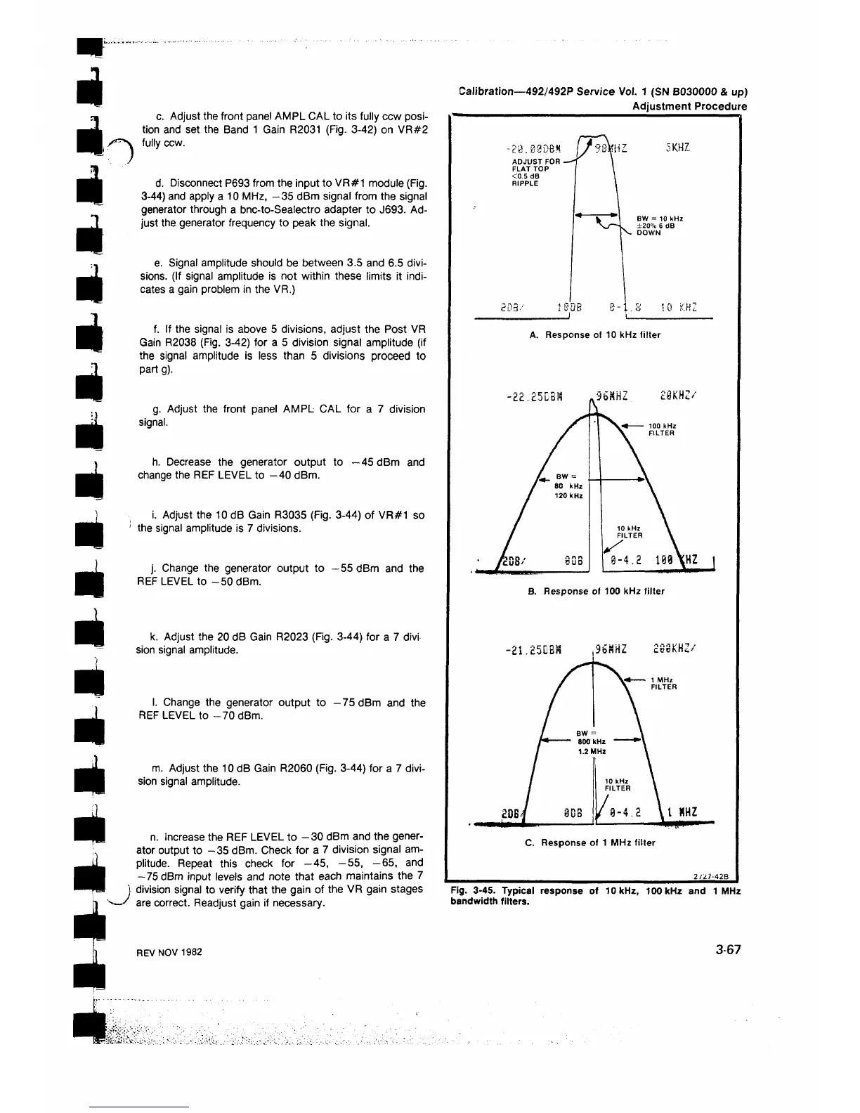
A. Response of 10 kHz filter
B. Response of 100 kHz filter
2 /2 ^ 2B
Fig. 3-45. Typical response of 10 kHz, 100 kHz and 1 MHz
bandwidth filters.
3-67
 Loading...


