o. Remove the 10 MHz signal to J680 and reconnect
P680. The final band gain level adjustments are described
after calibrating the Preselector Tracking and checking flat
ness. The mean level for each band is set to the level of
band 1 .
Calibration—492/492P Service Vol. 1 (SN B030000 & up)
Adjustment Procedure
step 3 of the Performance Check part. Output level is ad
justed with Cal Level, R1045 (Fig. 3-46). An adjustable ca
pacitor, C3031 within the cover, is only adjusted if the
oscillator fails to start. It is adjusted for maximum output. If
the Cal Level adjustment (R1045) should run out of range,
change the value of select resistor A34A1R1018.
12. Calibrator Output Level
The calibrator output level is calibrated to a known refer
ence. The procedure for checking the level is described in
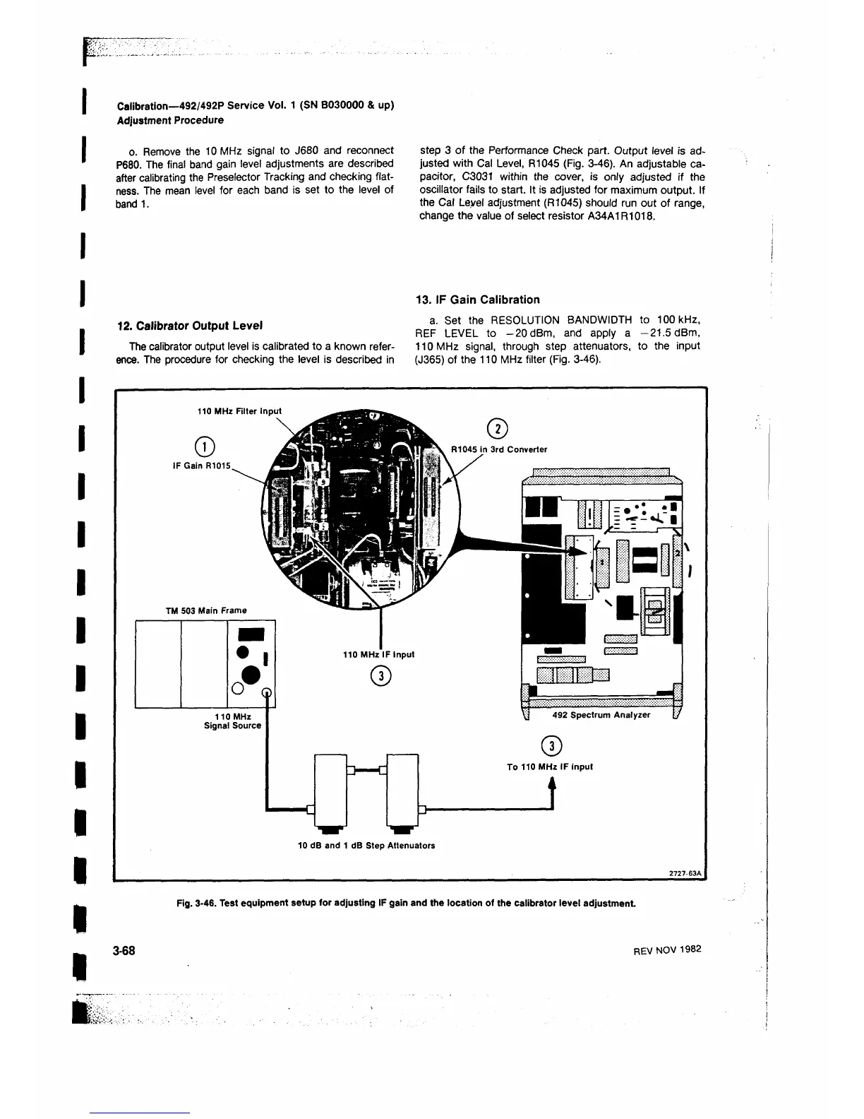
13. IF Gain Calibration
a. Set the RESOLUTION BANDWIDTH to 100 kHz,
REF LEVEL to -20 dBm, and apply a —21.5 dBm,
110 MHz signal, through step attenuators, to the input
(J365) of the 110 MHz filter (Fig. 3-46).
110 MHz Filter Input
©
IF Gain R1015,
TM 503 Main Frame
110 MHz
Signal Source
492 Spectrum Analyzer
To 110 MHz IF input
i
10 dB and 1 dB Step Attenuators
Fig. 3-46. Test equipment setup for adjusting IF gain and the location of the calibrator level adjustm ent
3-68
REV NOV 1982
 Loading...


