Adjust the following (Fig. 3-47) for SN B043114 and be
low to match the step waveform to the graticule:
Calibration—492/492P Service Vol. 1 (SN B030000 & up)
Adjustment Procedure
Assembly Adjustment
Horizontal Digital Storage Horizontal Offset, R3041
Horizontal Digital Storage Output Gain, R1040
Vertical Digital Storage Output Offset, R1036
Vertical Digital Storage Output Gain, R1024
Be sure that the left and right edges of the step
waveform coincide with the left and right edges of the
graticule. (This matches the horizontal display width of a
1 0 0 0 -point waveform to the graticule.)
g. Press FREE RUN and reduce the span to
200 kHz/div. Keep the signal centered with the FREQUEN
CY control.
h. Increase REF LEVEL for a signal peak about one divi
sion above the bottom of the graticule.
i. Cancel VIEW A, while pressing VIEW B repeatedly,
and adjust Vertical Offset R1030, on the Vertical Digital
Storage board to minimize the amplitude difference between
the stored and real-time waveforms.
j. Reduce REF LEVEL to bring the signal peak close to
the top of the graticule.
k. Again, while pressing VIEW B repeatedly, adjust Input
Gain R1034 on the Vertical Digital Storge board to minimize
the amplitude difference between the stored and real-time
waveforms.
I. Because the offset and gain adjustments interact, re
peat parts h through k as necessary.
m. Cancel the NARROW Video Filter.
n. Increase FREQ SPAN/DIV to 10 MHz and tune the
signal to within one division of the right edge of the graticule.
o. While pressing VIEW B repeatedly, adjust Input Gain
R1048 SN B043115 and above (R1045 SN B043114 and
below) on the Horizontal Digital Storage board, so the hori
zontal position of the stored signal matches that of the non-
stored signal.
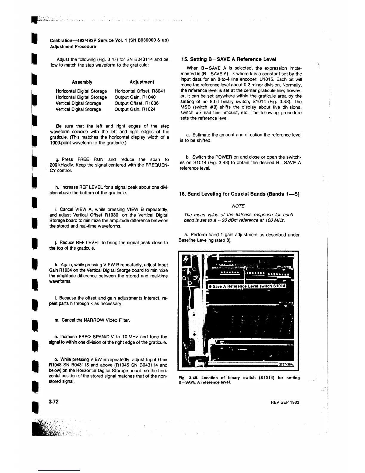
15. Setting B—SAVE A Reference Level
When B—SAVE A is selected, the expression imple
mented is (B—SAVE A )-k where k is a constant set by the
input data for an 8-to-4 line encoder, U1015. Each bit will
move the reference level about 0.2 minor division. Normally,
the reference level is set at the center graticule line; howev
er, it can be set anywhere within the graticule area by the
setting of an 8 -bit binary switch, S1014 (Fig. 3-48). The
MSB (switch # 8 ) shifts the display about five divisions,
switch #7 half this amount, etc. The following procedure
sets the reference level.
a. Estimate the amount and direction the reference level
is to be shifted.
b. Switch the POWER on and close or open the switch
es on S1014 (Fig. 3-48) to obtain the desired B—SAVE A
reference level.
16. Band Leveling for Coaxial Bands (Bands 1— 5)
NOTE
The mean value of the flatness response for each
band is set to a —20 dBm reference at 100 MHz.
a. Perform band 1 gain adjustment as described under
Baseline Leveling (step 8 ).
Fig. 3-48. Location of binary switch (S1014) for setting
B—SAVE A reference level.
3-72
REV SEP 1983
 Loading...


