Calibration—492/492P Service Vol. 1 (SN B030000 & up)
Adjustment Procedure
b. Perform flatness check of bands 1 through 5 as de
scribed under Frequency Response Check of the Perfor
mance Check and note the frequency at the mean level for
each band.
c. Set the front-panel controls as follows:
Vertical Display 2 dB/DIV
REF LEVEL -20 dBm
FREQ SPAN/DIV 10 MHz
RESOLUTION BANDWIDTH 1 MHz
TIME/DIV AUTO
Digital Storage (Option 02) VIEW A/VIEW B
17. Band Leveling for Waveguide Bands (Bands
6— 11)
a. Test equipment setup is shown in Fig. 3-50. Apply
2072 MHz at -58 dBm, through a dc-blocking capacitor to
the EXT MIXER input. Monitor the input with a power meter
to set the input level. Set the front-panel controls as follows:
FREQUENCY RANGE
FREQ SPAN/DIV
AUTO RESOLUTION
REF LEVEL
18—26 GHz (band 6 )
200 MHz
On
— 30 dBm
d. Switch the frequency range to band 2 (1.7—5.5 GHz)
and apply a calibrated -20 dBm signal whose frequency is
the same as that noted for the mean level in part b.
NOTE
The baseline of the display will rise when 2072 MHz
signal is applied to the EXT MIXER input port
connector.
NOTE
If a power meter is used to monitor signal level, con
nect the power meter sensor at the RF INPUT.
e. Tune the signal to center screen and reduce the
FREQ SPAN/DIV to either 1 MHz or 500 kHz.
f. Adjust band 2 Gain R3034 (Fig. 3-49), for a full screen
(-20 dBm) display.
g. Increase the FREQ SPAN/DJV to about 200 MHz and
change the FREQUENCY RANGE to band 3
(3.0—7.1 GHz). Apply a calibrated -20 dBm signal at the
frequency noted for the mean level in part b.
h. Tune the signal to center screen and again decrease
the span to about 500 kHz/Div with a RESOLUTION
BANDWIDTH of 1 MHz.
i. Adjust band 3 Gain R3030 (Fig. 3-49), for a full screen
display.
j. Repeat the above procedure for each coaxial band
(1—5) and set the gain of each with the appropriate adjust
m e n t
(see Fig. 3-49). If the range of any adjustment is insuf
ficient, . add or remove the appropriate diode (see
schematics and Fig. 3-49) to obtain the required range. Add
ing the diode increases gain.
b. With -60 dBm input level applied, adjust band 6 Gain
Leveling R3032 (Fig. 3-49), for full screen display.
c. Change the FREQUENCY RANGE and input signal
level as listed in Table 3-12. Adjust the appropriate Band
Gain adjustments (Fig. 3-49) for full screen display. Input
levels and gain adjustment for the waveguide bands need to
be adjusted only if these bands will be used.
d. Turn power off; replace VR module.
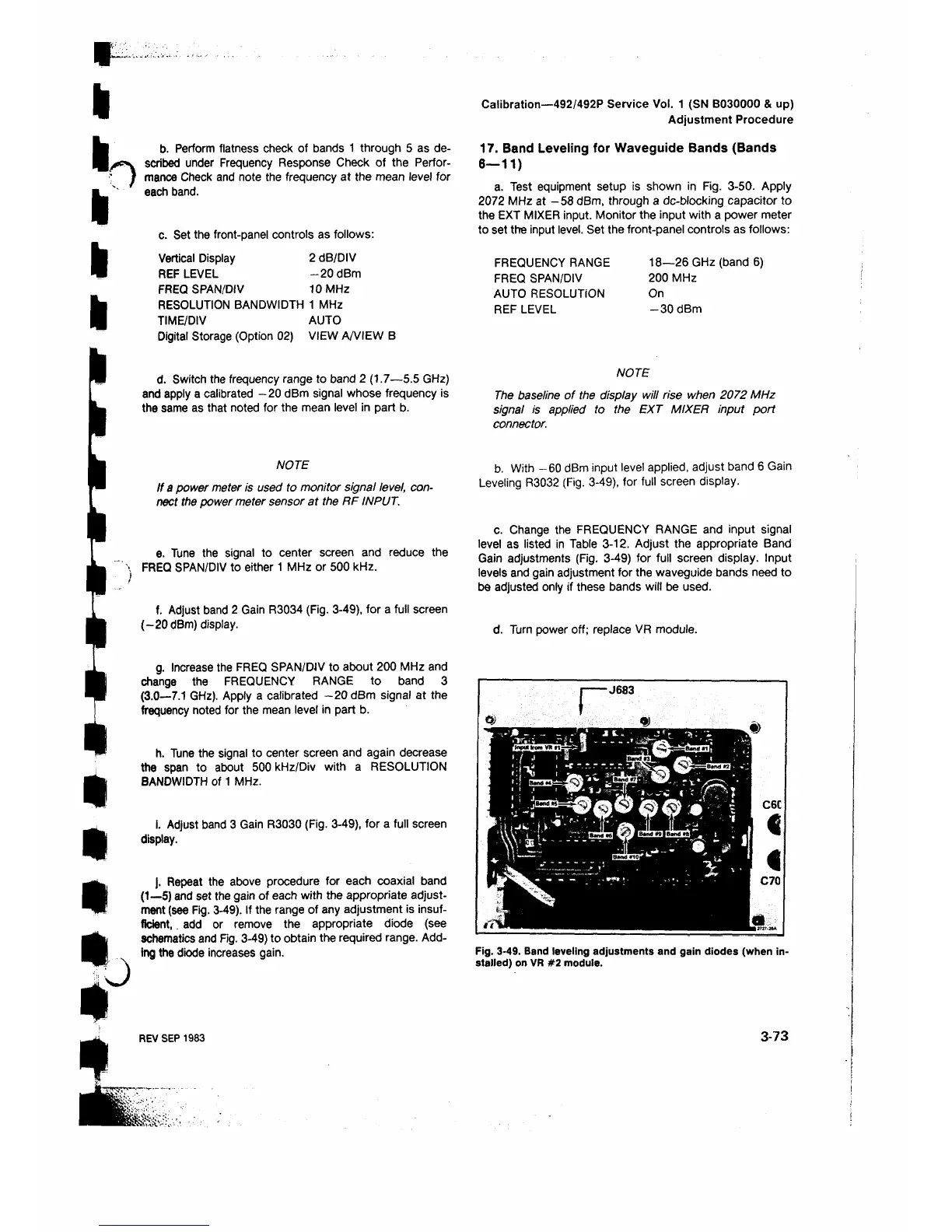
I------J683
Fig. 3-49. Band leveling adjustments and gain diodes (when in
stalled) on VR #2 module.
REV SEP 1983
3-73
 Loading...


