Calibration—492/492P Service Vol. 1 (SN B030000 & up)
Adjustment Procedure
Table 3-12
EXT MIXER BAND LEVELING ADJUSTMENTS
Band Input Level Gain
Adjustment
6(18—26 GHz)
— 60 dBm
R3024
7 (26—40 GHz)
— 60 dBm
R3026
8 (40—60 GHz)
— 60 dBm
R3032
9 (60—90 GHz)
—60 dBm
R3029
10(90—140 GHz) — 60 dBm R3028
11 (140—220 GHz)
— 60 dBm
R3028
18. Preselector Driver (Option 01) Calibration
a. Turn POWER off, pull Preselector Driver and install on
extender board (Fig. 3-51), then switch POWER on.
b. Set the offset for driver U2054 as follows: (Offset
should only require adjusting if U2054 is changed.)
1) set the FREQUENCY RANGE to band 1
(0—1.8 GHz);
2) pull P3055 and connect a voltmeter between TP4054
and analog ground (Fig. 3-52). Set the voltmeter range to
30 μν or less;
3) adjust Driver Offset R2066 (Fig. 3-52) for 0 V;
4) disconnect meter and replace P3055;
5) turn POWER off, reinstall Preselector Driver board
and switch POWER on.
c. Connect digital multimeter between center tap of
PEAKING potentiometer and ground. Adjust the control for
0 V indication. If index on the knob is not aligned with the
mark on the front panel, loosen knob and position the mark
so it is aligned.
d. Apply the CAL OUT signal to the RF INPUT. Set the
REF LEVEL to -30 dBm, FREQ SPAN/DIV to 20 MHz and
activate AUTO RESOLUTION. Select the 1.7—5.5 GHz
FREQUENCY RANGE and adjust the FREQUENCY to cen
ter the 2.1 GHz marker. Center Input Offset adjustment
R1031 (Fig. 3-52), press DEGAUSS button, and then center
the 2.1 GHz marker on screen with the FREQUENCY
control.
e. Ground TP1069 (Fig. 3-52), with a jumper strap and
adjust the Preselector Offset (R1064) for maximum re
sponse of the 2.1 GHz signal. Remove the grounding strap
and press DEGAUSS button.
f. Peak the 2.1 GHz signal with the -829 MHz IF Offset,
R1049 (Fig. 3-52).
g. Remove the Calibrator signal to the RF INPUT and
connect the output of the microwave comb generator to the
RF INPUT (see Fig. 3-51). Change the REF LEVEL to
0 dBm. Now tune the CENTER FREQUENCY to 5.5 GHz
and center the 5.5 GHz comb marker on screen. Press
DEGAUSS, then recenter the 5.5 GHz signal.
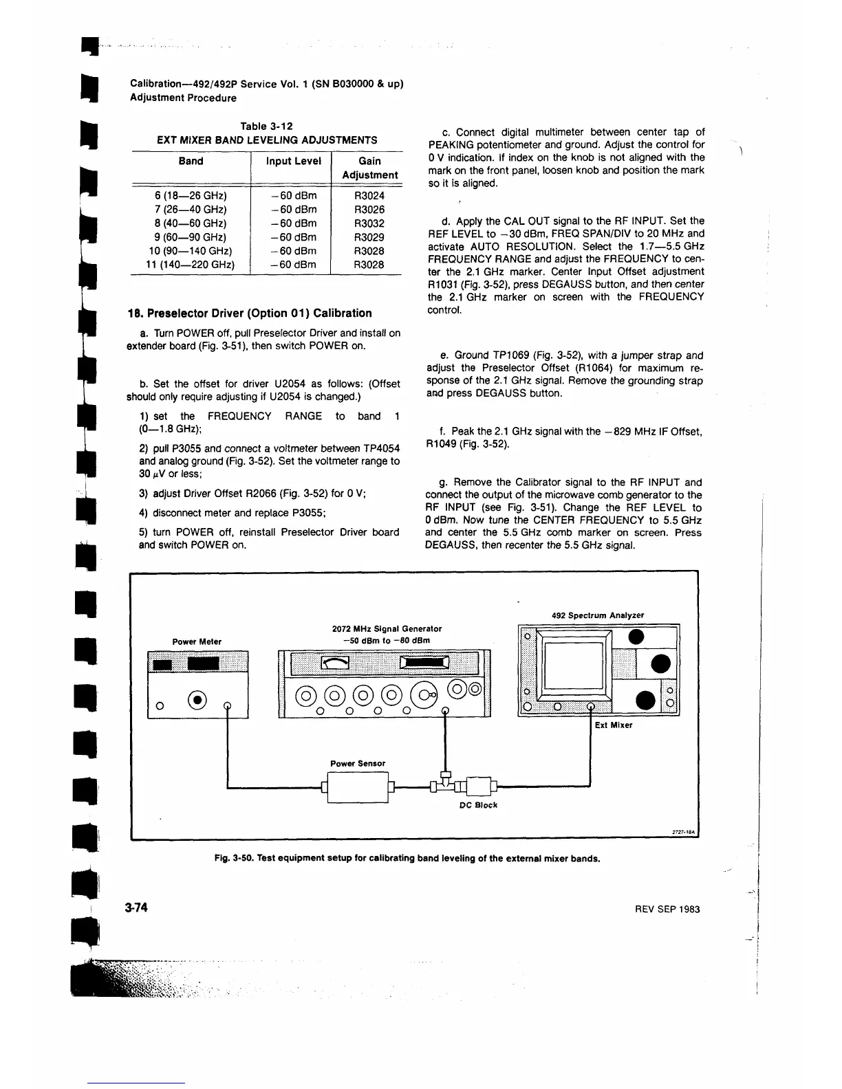
492 Spectrum Analyzer
Fig. 3-50. Test equipment setup for calibrating band leveling of the external mixer bands.
3-74
REV SEP 1983
 Loading...


