Maintenance—492/492P Service Vol. 1 (SN B030000 & up)
Fig. 4-1. Multipin (harmonica) connector configuration.
Diode Color Code. The cathode of each glass encased
diode is indicated by a stripe, a series of stripes, or a dot.
Some diodes have a diode symbol printed on one side. Fig
ure 4-3 illustrates diode types and polarity markings that are
used in this instrument.
Transistor and Integrated Circuit Electrode Configura
tion. Lead identification for the transistors and MOS FET’s
is shown in Fig. 4-4. IC pin outs are shown either by table or
box on the schematic diagram.
Semiconductor failures account for the majority of elec
tronic equipment failures. Most semiconductors are
soldered to the boards. The following guidelines should be
observed when substituting these components.
NOTE
Before using any test equipment to make measure
ments on static-sensitive components or assemblies,
be certain that any voltage or current supplied by the
test equipment does not exceed the limits o f the com
ponents to be tested.
a. Try to isolate the problem to a component through
signal analysis. Determine that circuit voltages will not dam
age the replacement.
b. Turn the power off before removing a component.
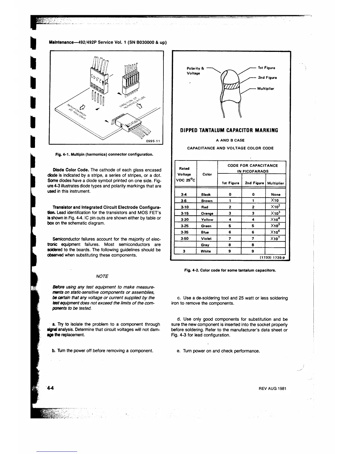
DIPPED TANTALUM CAPACITOR MARKING
A A N D B CASE
CAPACITANCE AND VOLTAGE COLOR CODE
Rated
Voltage
VDC 25°C
Color
CODE FOR CAPACITANCE
IN PICOFARADS
1st Figure 2nd Figure
Multiplier
3-4 Black
0 0
None
3-6
Brown
1 1
X10
3-10 Red 2 2 X10²
3-15 Orange
3 3
X103
3-20
Yellow 4 4
X104
3-25 Green 5
5
X105
3-35 Blue
6
6
Xio6
3-50 Violet 7
7
X107
Gray 8
8
3 White
9
9
( 1 7 3 3 ) 1 7 3 5 - 9
Fig. 4-2. Color code for some tantalum capacitors.
c. Use a de-soldering tool and 25 watt or less soldering
iron to remove the components.
d. Use only good components for substitution and be
sure the new component is inserted into the socket properly
before soldering. Refer to the manufacturer’s data sheet or
Fig. 4-3 for lead configuration.
e. Turn power on and check performance.
4-4
REV AUG 1981
 Loading...


