Maintenance—492/492P Service Vol. 1 (SN B030000 & up)
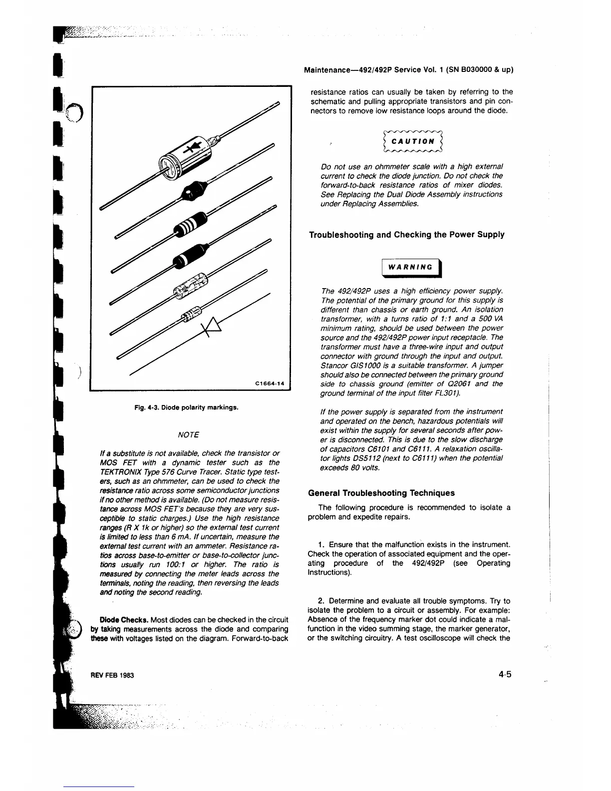
Fig. 4-3. Diode polarity markings.
NOTE
If a substitute is not available, check the transistor or
MOS FET with a dynamic tester such as the
TEKTRONIX Type 576 Curve Tracer. Static type test
ers, such as an ohmmeter, can be used to check the
resistance ratio across some semiconductor junctions
if no other method is available. (Do not measure resis
tance across MOS FET's because they are very sus
ceptible to static charges.) Use the high resistance
ranges (R X 1k or higher) so the external test current
is limited to less than 6 mA. If uncertain, measure the
external test current with an ammeter. Resistance ra
tios across base-to-emitter or base-to-collector junc
tions usually run 100:1 or higher. The ratio is
measured by connecting the meter leads across the
terminals, noting the reading, then reversing the leads
and noting the second reading.
Diode Checks. Most diodes can be checked in the circuit
by taking measurements across the diode and comparing
these with voltages listed on the diagram. Forward-to-back
REV FEB 1983
resistance ratios can usually be taken by referring to the
schematic and pulling appropriate transistors and pin con
nectors to remove low resistance loops around the diode.
) CAUTION <
Do not use an ohmmeter scale with a high external
current to check the diode junction. Do not check the
forward-to-back resistance ratios of mixer diodes.
See Replacing the Dual Diode Assembly instructions
under Replacing Assemblies.
Troubleshooting and Checking the Power Supply
WARNING
The 492/492P uses a high efficiency power supply.
The potential of the primary ground for this supply is
different than chassis or earth ground. An isolation
transformer, with a turns ratio of 1:1 and a 500 VA
minimum rating, should be used between the power
source and the 492/492P power input receptacle. The
transformer must have a three-wire input and output
connector with ground through the input and output.
Stancor GIS 1000 is a suitable transformer. A jumper
should also be connected between the primary ground
side to chassis ground (emitter of 02061 and the
ground terminal of the input filter FL301).
If the power supply is separated from the instrument
and operated on the bench, hazardous potentials will
exist within the supply for several seconds after pow
er is disconnected. This is due to the slow discharge
of capacitors C6101 and 06111. A relaxation oscilla
tor lights DS5112 (next to 06111) when the potential
exceeds 80 volts.
General Troubleshooting Techniques
The following procedure is recommended to isolate a
problem and expedite repairs.
1. Ensure that the malfunction exists in the instrument.
Check the operation of associated equipment and the oper
ating procedure of the 492/492P (see Operating
Instructions).
2. Determine and evaluate all trouble symptoms. Try to
isolate the problem to a circuit or assembly. For example:
Absence of the frequency marker dot could indicate a mal
function in the video summing stage, the marker generator,
or the switching circuitry. A test oscilloscope will check the
4-5
 Loading...


