Maintenance—492/492P Service Vol. 1 (SN B030000 & up)
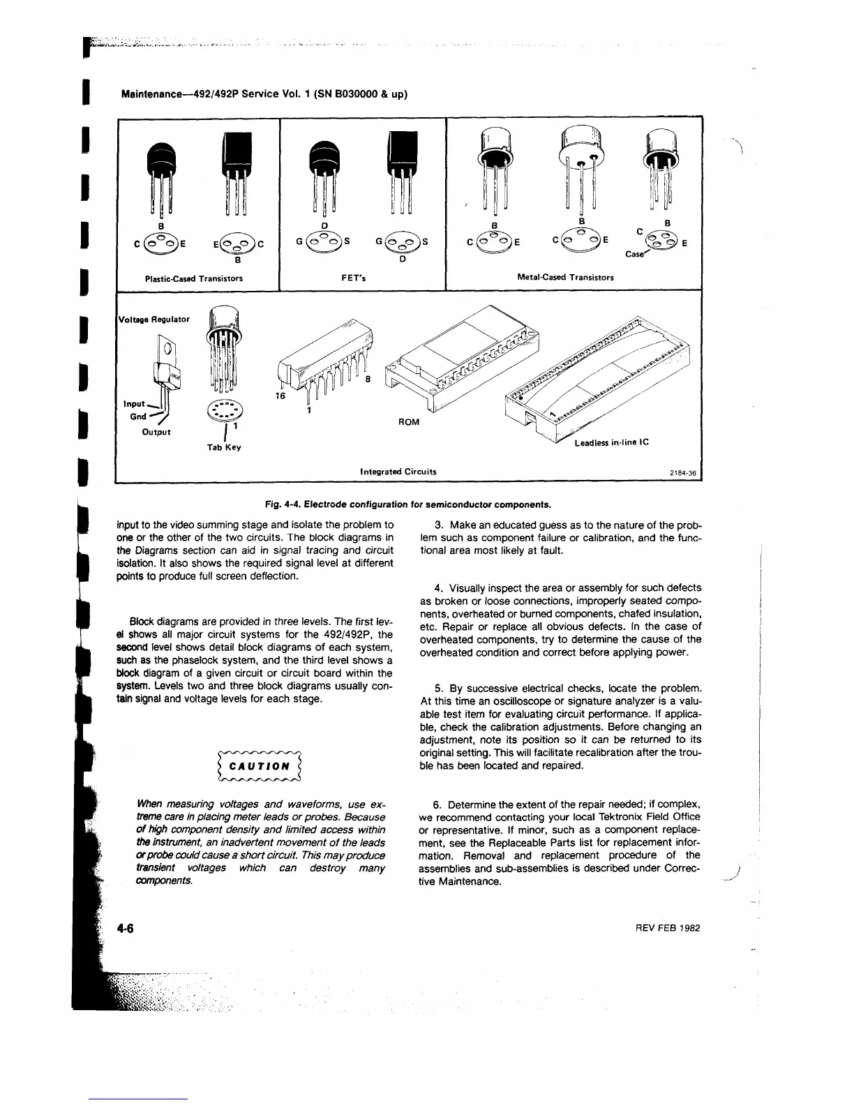
Fig. 4-4. Electrode configuration for semiconductor components.
input to the video summing stage and isolate the problem to
one or the other of the two circuits. The block diagrams in
the Diagrams section can aid in signal tracing and circuit
isolation. It also shows the required signal level at different
points to produce full screen deflection.
Block diagrams are provided in three levels. The first lev
el shows all major circuit systems for the 492/492P, the
second level shows detail block diagrams of each system,
such as the phaselock system, and the third level shows a
block diagram of a given circuit or circuit board within the
system. Levels two and three block diagrams usually con
tain signal and voltage levels for each stage.
When measuring voltages and waveforms, use ex
treme care in placing meter leads or probes. Because
of high component density and limited access within
the instrument, an inadvertent movement of the leads
or probe could cause a short circuit. This may produce
transient voltages which can destroy many
components.
3. Make an educated guess as to the nature of the prob
lem such as component failure or calibration, and the func
tional area most likely at fault.
4. Visually inspect the area or assembly for such defects
as broken or loose connections, improperly seated compo
nents, overheated or burned components, chafed insulation,
etc. Repair or replace all obvious defects. In the case of
overheated components, try to determine the cause of the
overheated condition and correct before applying power.
5. By successive electrical checks, locate the problem.
At this time an oscilloscope or signature analyzer is a valu
able test item for evaluating circuit performance. If applica
ble, check the calibration adjustments. Before changing an
adjustment, note its position so it can be returned to its
original setting. This will facilitate recalibration after the trou
ble has been located and repaired.
6 . Determine the extent of the repair needed; if complex,
we recommend contacting your local Tektronix Field Office
or representative. If minor, such as a component replace
ment, see the Replaceable Parts list for replacement infor
mation. Removal and replacement procedure of the
assemblies and sub-assemblies is described under Correc
tive Maintenance.
4-6
REV FEB 1982
 Loading...


