Maintenance—492/492P Service Vol. 1 (SN B030000 & up)
DC BLOCK
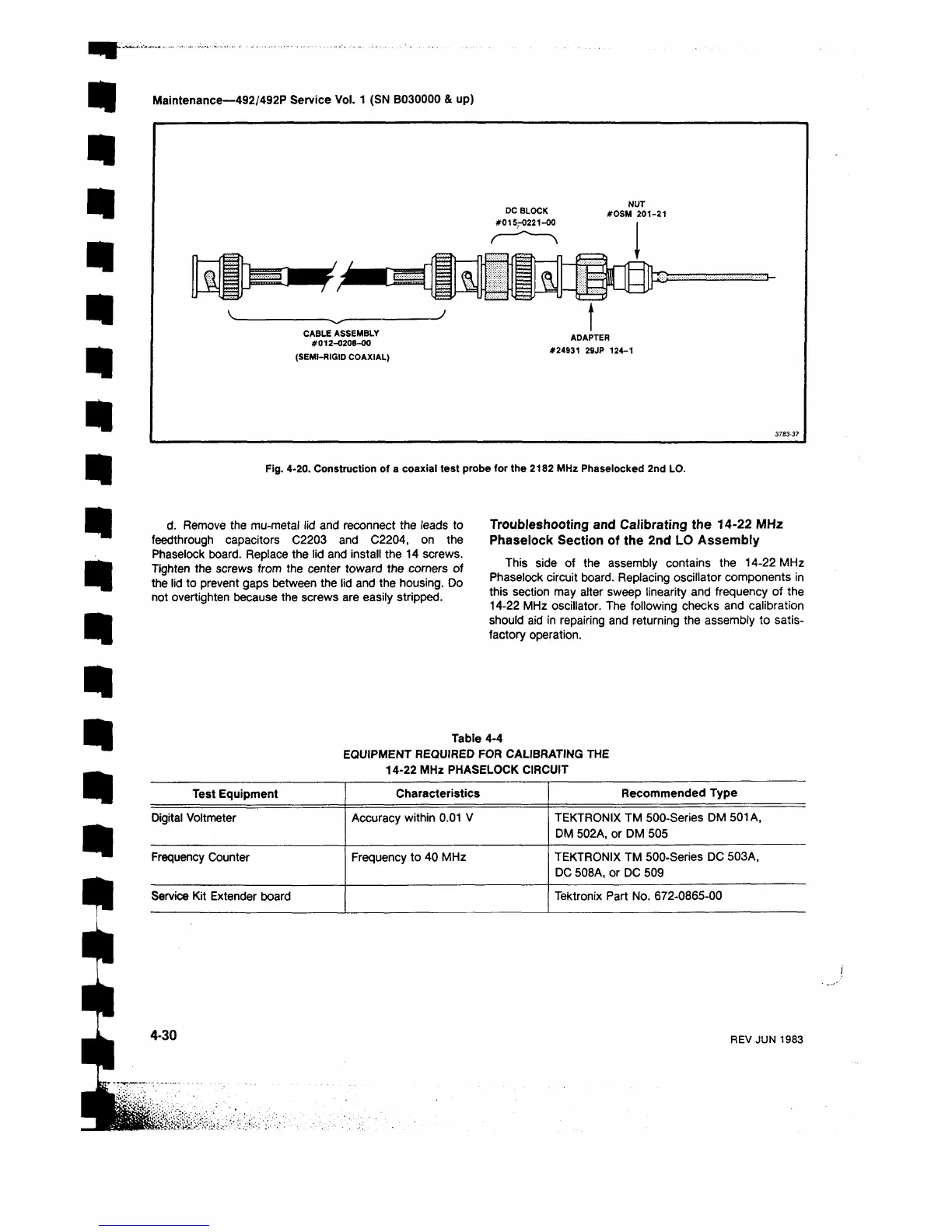
#015-0221-00
NUT
#OSM 201-21
S O
CABLE ASSEMBLY
#012-0208-00
(SEMI-RIGID COAXIAL)
ADAPTER
#24931 29JP 124-1
3763-3?
Fig. 4-20. Construction of a coaxial test probe for the 2182 MHz Phaselocked 2nd LO.
d. Remove the mu-metal lid and reconnect the leads to
feedthrough capacitors C2203 and C2204, on the
Phaselock board. Replace the lid and install the 14 screws.
Tighten the screws from the center toward the corners of
the lid to prevent gaps between the lid and the housing. Do
not overtighten because the screws are easily stripped.
Troubleshooting and Calibrating the 14-22 MHz
Phaselock Section of the 2nd LO Assembly
This side of the assembly contains the 14-22 MHz
Phaselock circuit board. Replacing oscillator components in
this section may alter sweep linearity and frequency of the
14-22 MHz oscillator. The following checks and calibration
should aid in repairing and returning the assembly to satis
factory operation.
Table 4-4
EQUIPMENT REQUIRED FOR CALIBRATING THE
14-22 MHz PHASELOCK CIRCUIT
Test Equipment
Characteristics
Recommended Type
Digital Voltmeter Accuracy within 0.01 V
TEKTRONIX TM 500-Series DM 501 A,
DM 502A, or DM 505
Frequency Counter
Frequency to 40 MHz
TEKTRONIX TM 500-Series DC 503A,
DC 508A, or DC 509
Service Kit Extender board
Tektronix Part No. 672-0865-00
4-30
REV JUN 1983
 Loading...


