Maintenance—492/492P Service Vol. 1 (SN B030000 & up)
1. Preliminary
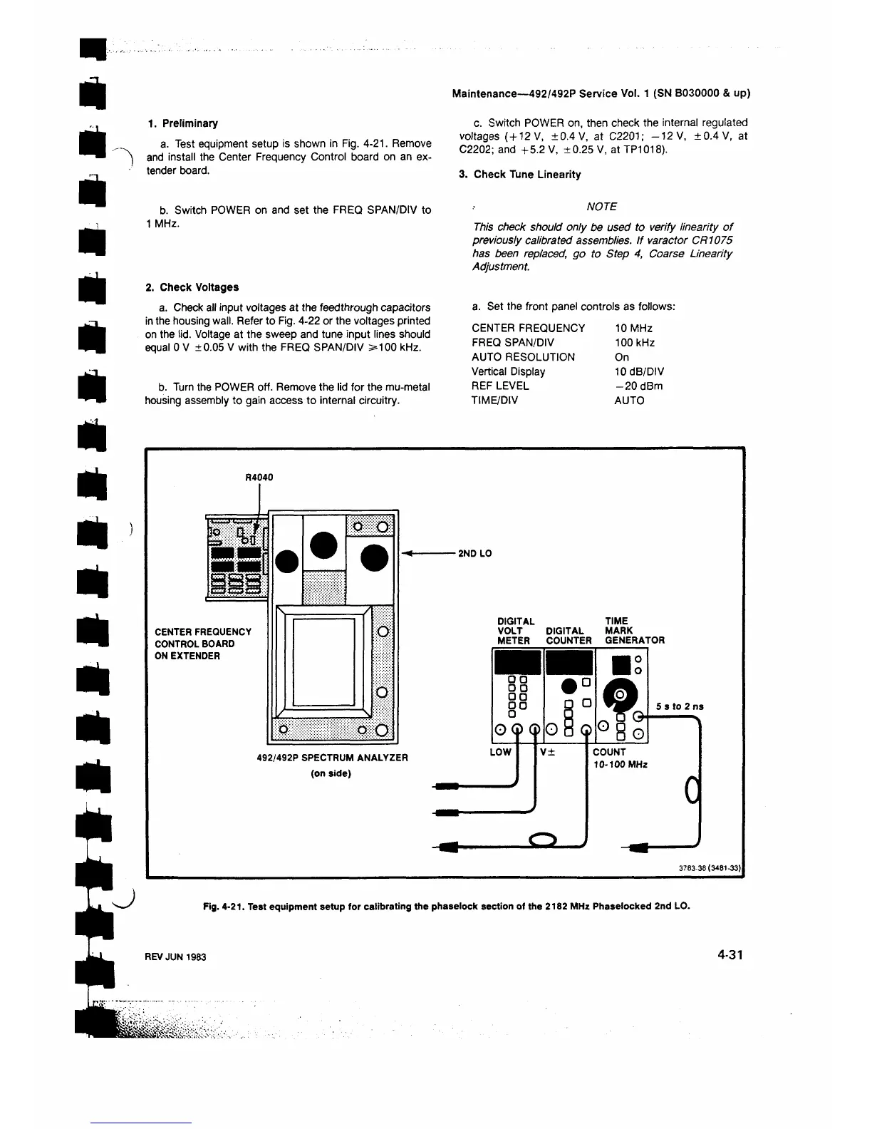
a. Test equipment setup is shown in Fig. 4-21. Remove
and install the Center Frequency Control board on an ex
tender board.
c. Switch POWER on, then check the internal regulated
voltages (+12 V, ±0.4 V, at C2201; -1 2 V, ±0.4V, at
C2202; and +5.2 V, ±0.25 V, at TP1018).
3. Check Tune Linearity
b. Switch POWER on and set the FREQ SPAN/DIV to
1 MHz.
2. Check Voltages
a. Check all input voltages at the feedthrough capacitors
in the housing wall. Refer to Fig. 4-22 or the voltages printed
on the lid. Voltage at the sweep and tune input lines should
equal 0 V ±0.05 V with the FREQ SPAN/DIV >100 kHz.
b. Turn the POWER off. Remove the lid for the mu-metal
housing assembly to gain access to internal circuitry.
NOTE
This check should only be used to verify linearity of
previously calibrated assemblies. If varactor CR1075
has been replaced, go to Step 4, Coarse Linearity
Adjustment.
a. Set the front panel controls as follows:
CENTER FREQUENCY 10 MHz
FREQ SPAN/DIV
100 kHz
AUTO RESOLUTION On
Vertical Display
10 dB/DIV
REF LEVEL -2 0 dBm
TIME/DIV
AUTO
R4040
CENTER FREQUENCY
CONTROL BOARD
ON EXTENDER
m m
o
D
ο O
492/492P SPECTRUM ANALYZER
(on side)
■ 2ND LO
DIGITAL TIME
VOLT DIGITAL MARK
METER COUNTER GENERATOR
3 7 8 3 -3 8 (3 4 8 1 -3 3 )
Fig. 4-21. Test equipment setup for calibrating the phaselock section of the 2182 MHz Phaselocked 2nd LO.
REV JUN 1983
4-31
 Loading...


