Maintenance—492/492P Service Vol. 1 (SN B030000 & up)
MICROCOMPUTER SYSTEM MAINTENANCE
Several maintenance aids are built into the
microcomputer system. These are microcomputer operating
modes that demonstrate correct performance or indicate
the location of a problem, if any.
Switches that set up two of these test modes are de
scribed first, followed by instructions for the three test
modes. In the first mode, the microcomputer executes a
self-test that verifies, in so far as possible, correct oper
ation. RAM, ROM, and interface adapters are checked; any
failure found is indicated.
The second mode hardwires the microcprocessor to ex
ecute an instruction that toggles the address bus; this mode
requires less of the system to run, so may be used to
troubleshoot problems that disable the first mode.
The third mode gets at communication between the
microcomputer and the rest of the instrument. The
microcomputer exercises the instrument bus to help isolate
problems that do not show up in the first mode, but prevent
normal instrument operation because of a breakdown in
communication.
Some notes on operation of several versions of instru
ment firmware conclude the discussion of microcomputer
system maintenance.
Memory Board Option Switch
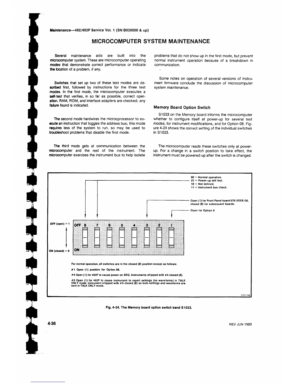
S1033 on the Memory board informs the microcomputer
whether to configure itself at power-up for several test
modes, for instrument modifications, and for Option 08. Fig
ure 4-24 shows the correct setting of the individual switches
in S1033.
The microcomputer reads these switches only at power-
up. For a change in a switch position to take effect, the
instrument must be powered-up after the switch is changed.
OFF (open) :
ON (closed) = 0
00 = Normal operation.
01 = Power-up self test.
10 = Not defined.
11 = Instrument bus check.
Open (1) for Front Panel board 670-ΧΧΧΧ-00,
closed (0) for subsequent boards.
Open for Option 8
For normal operation, all switches are in the closed (0) position except as follows:
#1 Open (1) position for Option 08.
#4 Open (1) for 492P to cause power on SRQ. Instruments shipped with #4 closed (0).
#5 Open (1) for 492P to cause instrument to report settings (no waveforms) in TALK
ONLY mode. Instrument shipped with #5 closed (0) so both settings and waveforms are
sent in TALK ONLY mode.
Fig. 4-24. The Memory board option switch band S1033.
4-36
REV JUN 1983
 Loading...


