Theory of Operation—492/492P Service Vol. 1 (SN B030000 & up)
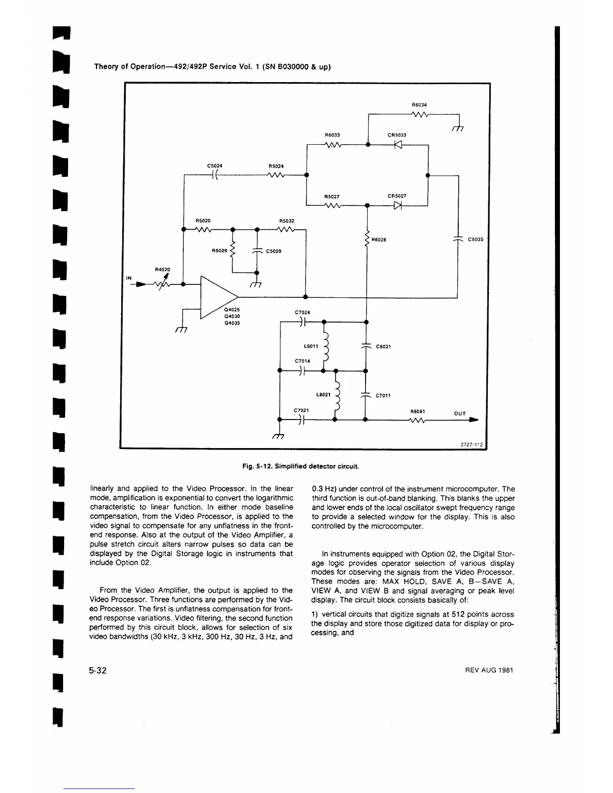
Fig. 5-12. Simplified detector circuit.
linearly and applied to the Video Processor. In the linear
mode, amplification is exponential to convert the logarithmic
characteristic to linear function. In either mode baseline
compensation, from the Video Processor, is applied to the
video signal to compensate for any unflatness in the front-
end response. Also at the output of the Video Amplifier, a
pulse stretch circuit alters narrow pulses so data can be
displayed by the Digital Storage logic in instruments that
include Option 02.
From the Video Amplifier, the output is applied to the
Video Processor. Three functions are performed by the Vid
eo Processor. The first is unflatness compensation for front-
end response variations. Video filtering, the second function
performed by this circuit block, allows for selection of six
video bandwidths (30 kHz, 3 kHz, 300 Hz, 30 Hz, 3 Hz, and
0.3 Hz) under control of the instrument microcomputer. The
third function is out-of-band blanking. This blanks the upper
and lower ends of the local oscillator swept frequency range
to provide a selected window for the display. This is also
controlled by the microcomputer.
In instruments equipped with Option 02, the Digital Stor
age logic provides operator selection of various display
modes for observing the signals from the Video Processor.
These modes are: MAX HOLD, SAVE A, B-SAVE A,
VIEW A, and VIEW B and signal averaging or peak level
display. The circuit block consists basically of:
1) vertical circuits that digitize signals at 512 points across
the display and store those digitized data for display or pro
cessing, and
5-32
REV AUG 1981
 Loading...


