Theory of Operation—492/492P Service Vol. 1 (SN B030000 & up)
2) horizontal circuits that translate the sweep signal into
memory address into which the signal data are stored. The
stored signals are then used for the various processing as
required by operator display selection, and for recreation of
the display. From the Digital Storage logic, horizontal and
vertical signals for the recreated displays are applied to the
Deflection Amplifiers.
The Deflection Amplifiers receive vertical signals from the
Digital Storage (in Option 02 instruments), or the Video Pro
cessor, and sweep voltage from the Sweep section, along
with readout data from the Crt Readout circuits and
produce signals to drive the crt for the display. In Option 02
instruments, the Digital Storage or Video Processor vertical
outputs may be selected. In non-Option 02 instruments, the
Video Processor output is displayed. Likewise, horizontal
signals from either the Digital Storage logic or the Sweep
section can be selected. During the display segments in
which digital crt readout is required, the Deflection Amplifi
ers input signals are supplied by the Crt Readout logic. The
amplifier contains the switching circuits to perform the
above selection functions, and amplifier stages to produce
the plate drive signals.
Crt readout data is controlled by the Crt Readout logic.
These circuits generate letters and numbers for display un
der control of the microcomputer. Using data received from
the data bus, a character memory and generator circuit de
rives each character. Digital signals, describing each charac
ter, are then translated into deflection signals by digital-to-
analog converters. These signals are applied to the
switching logic in the Deflection Amplifiers.
Beam intensity, nominally from the front panel, is imple
mented in the Z-Axis logic. Unblanking for display of either
signals or readout data, and baseline clipping is also imple
mented in the Z-Axis logic. Control of unblanking is by sig
nals from the Sweep section, the Crt Readout logic, the
Deflection Amplifiers, and the Digital Storage logic.
VIDEO AMPLIFIER <^>
Refer to the block diagram adjacent to Diagram 22. The
Video Amplifier circuits provide for the selection of either
logarithmic or linear display mode, for the selection of dB
per division in logarithmic mode, for selection of pulse
stretching in narrow peak signal operations, and for offset
ting the signal amplitude during the signal identify mode.
These circuits consist of the log mode amplification and
dB/div switching circuits, the linear mode amplification and
gain control circuits, the pulse stretch circuit, and the var
ious digital control circuits.
Log Mode Circuits
The Log Mode circuits accept the VIDEO signal from the
Log Amplifier and process that signal to add offset for se
lecting the segment of the log amplifier gain curve to be
displayed. It also allows for selection, under program control
in the 492P, of display gain steps of 1 to 15 dB per division
on the screen. (Only 2 dB and 10 dB/Div are selectable from
the front panel. The 492P can select all steps under pro
gram control.)
The signal from the Log Amplifier is applied to
preamplifier U4090A. The VIDEO 1 signal from the Video
Processor is also applied to U4090A. This signal compen
sates for flatness errors in the front-end circuits by offset
ting the VIDEO signal in the opposite direction equal to the
unflatness. The two signals are summed at the input of
U4090B with the reference level set by Input Reference Lev
el potentiometer R4071 (this reference level will be de
scribed later) and with the output from digital-to-analog
converter U5041.
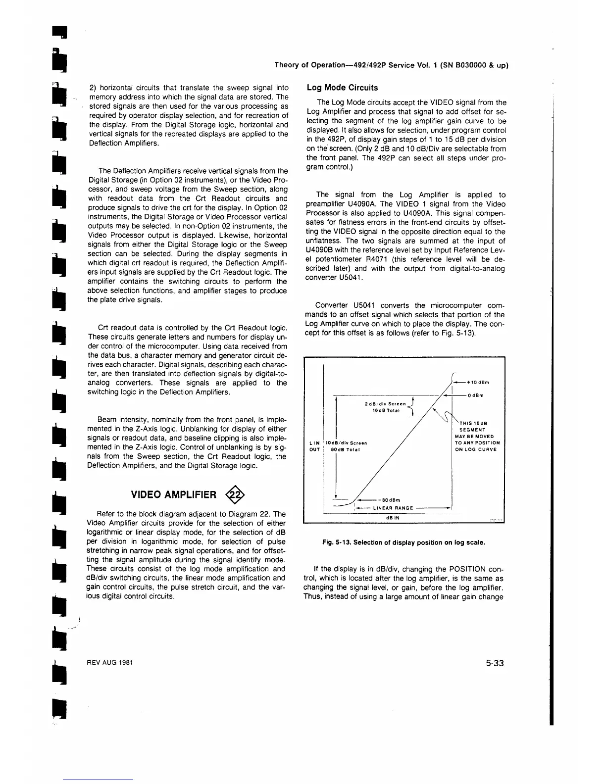
Converter U5041 converts the microcomputer com
mands to an offset signal which selects that portion of the
Log Amplifier curve on which to place the display. The con
cept for this offset is as follows (refer to Fig. 5-13).
Fig. 5-13. Selection of display position on log scale.
If the display is in dB/div, changing the POSITION con
trol, which is located after the log amplifier, is the same as
changing the signal level, or gain, before the log amplifier.
Thus, instead of using a large amount of linear gain change
REV AUG 1981
5-33
 Loading...


