Theory of Operation—492/492P Service Vol. 1 (SN B030000 & up)
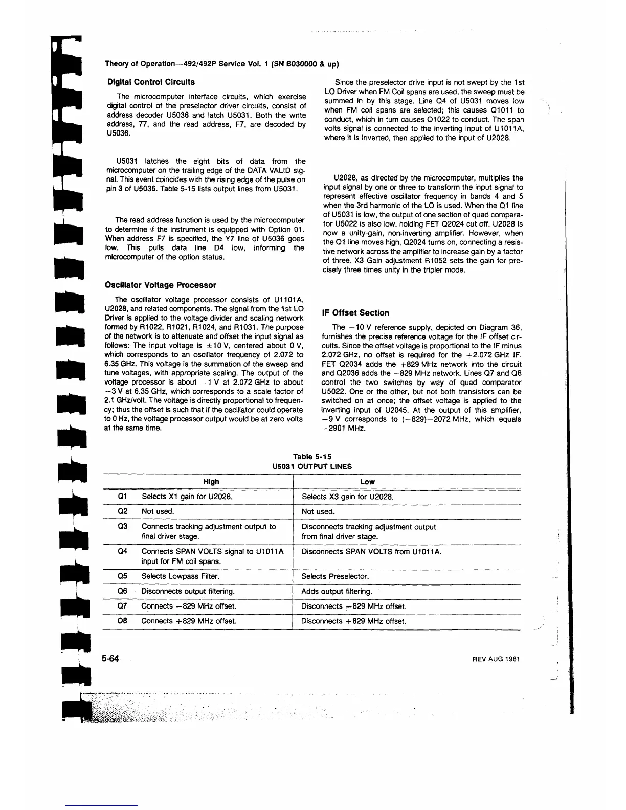
Digital Control Circuits
The microcomputer interface circuits, which exercise
digital control of the preselector driver circuits, consist of
address decoder U5036 and latch U5031. Both the write
address, 77, and the read address, F7, are decoded by
U5036.
Since the preselector drive input is not swept by the 1 st
LO Driver when FM Coil spans are used, the sweep must be
summed in by this stage. Line Q4 of U5031 moves low
when FM coil spans are selected; this causes Q1011 to
conduct, which in turn causes Q1022 to conduct. The span
volts signal is connected to the inverting input of U1011A,
where it is inverted, then applied to the input of U2028.
m
m
m
m
Λ
U5031 latches the eight bits of data from the
microcomputer on the trailing edge of the DATA VALID sig
nal. This event coincides with the rising edge of the pulse on
pin 3 of U5036. Table 5-15 lists output lines from U5031.
The read address function is used by the microcomputer
to determine if the instrument is equipped with Option 01.
When address F7 is specified, the Y7 line of U5036 goes
low. This pulls data line D4 low, informing the
microcomputer of the option status.
Oscillator Voltage Processor
The oscillator voltage processor consists of U1101A,
U2028, and related components. The signal from the 1 st LO
Driver is applied to the voltage divider and scaling network
formed by R1022, R1021, R1024, and R1031. The purpose
of the network is to attenuate and offset the input signal as
follows: The input voltage is ±10V, centered about 0 V,
which corresponds to an oscillator frequency of 2.072 to
6.35 GHz. This voltage is the summation of the sweep and
tune voltages, with appropriate scaling. The output of the
voltage processor is about -1 V at 2.072 GHz to about
—3 V at 6.35 GHz, which corresponds to a scale factor of
2.1 GHz/volt. The voltage is directly proportional to frequen
cy; thus the offset is such that if the oscillator could operate
to 0 Hz, the voltage processor output would be at zero volts
at the same time.
U2028, as directed by the microcomputer, multiplies the
input signal by one or three to transform the input signal to
represent effective oscillator frequency in bands 4 and 5
when the 3rd harmonic of the LO is used. When the Q1 line
of U5031 is low, the output of one section of quad compara
tor U5022 is also low, holding FET Q2024 cut off. U2028 is
now a unity-gain, non-inverting amplifier. However, when
the Q1 line moves high, Q2024 turns on, connecting a resis
tive network across the amplifier to increase gain by a factor
of three. X3 Gain adjustment R1052 sets the gain for pre
cisely three times unity in the tripler mode.
IF Offset Section
The —10 V reference supply, depicted on Diagram 36,
furnishes the precise reference voltage for the IF offset cir
cuits. Since the offset voltage is proportional to the IF minus
2.072 GHz, no offset is required for the +2.072 GHz IF.
FET Q2034 adds the + 829 MHz network into the circuit
and Q2036 adds the -829 MHz network. Lines Q7 and Q8
control the two switches by way of quad comparator
U5022. One or the other, but not both transistors can be
switched on at once; the offset voltage is applied to the
inverting input of U2045. At the output of this amplifier,
-9 V corresponds to (-829)-2072 MHz, which equals
-2901 MHz.
Table 5-15
U5031 OUTPUT LINES
High
Low
Q1 Selects X1 gain for U2028.
Selects X3 gain for U2028.
Q2
Not used.
Not used.
Q3
Connects tracking adjustment output to
final driver stage.
Disconnects tracking adjustment output
from final driver stage.
Q4
Connects SPAN VOLTS signal to U1011A
input for FM coil spans.
Disconnects SPAN VOLTS from U1011A.
Q5
Selects Lowpass Filter. Selects Preselector.
Q6
Disconnects output filtering. Adds output filtering.
Q7
Connects -829 MHz offset.
Disconnects —829 MHz offset.
Q8
Connects +829 MHz offset. Disconnects +829 MHz offset.
5-64
REV AUG 1981


 To Next Page
 Loading...