Theory of Operation—492/492P Service Vol. 1 (SN B030000 & up)
one, and the circuit is queried to find if the DAC output and
integrator output is greater or less than required. If less, the
microcomputer loads the next lower bit in addition and que
ries the circuit once more. This process goes on until the
two values are the same. Had the microcomputer found that
the DAC output was greater than the integrator output at
the first inquiry, it would have set the highest order bit to
zero and loaded the second-order bit into the low-order
DAC, then continued to load successively lower order bits,
one at a time, until the circuit signalled that the comparison
had reversed. By this process, which is known as the
successive approximation method, the circuit finally reaches
the point where the outputs are equal, and the
microcomputer commands the circuit to shift back to the
track mode.
Digital Control
The digital control circuits consist of buffer U2016, ad
dress decoder U2014, steering register U2022, and the
steering gates (U2024A, U2024B, U2024D, U2026A,
U2026B, and U2026C). Because of the quantity of data that
must pass through these circuits, a steering register is used
that has a separate address. The first byte of data, which is
the steering byte, is clocked into U2022 by the ADDRESS
70 signal. The output levels are applied to the steering
gates, and the circuit waits for the next byte. The micro
computer then furnishes the first byte of data to be sent to
low-order fine-tune digital-to-analog converter DAC, for ex
ample, by way of storage register U3022. The byte is
clocked into the register by the coincidence of low states at
the inputs of U2026C; one from the steering byte, and the
other from the ADDRESS 71 signal, which is used to clock
the steered data bytes into the correct register. This contin
ues until seven bytes of data have been clocked into the
circuits, including the steering byte. The third output from
U2014, ADDRESS 80, controls transistors Q2043 and
Q1039, which enable the write-back function.
In addition to the six steering lines that drive the steering
gates, U2022 also controls, by means of the Q1 and Q8
lines, the hold/track selector transistor for each converter
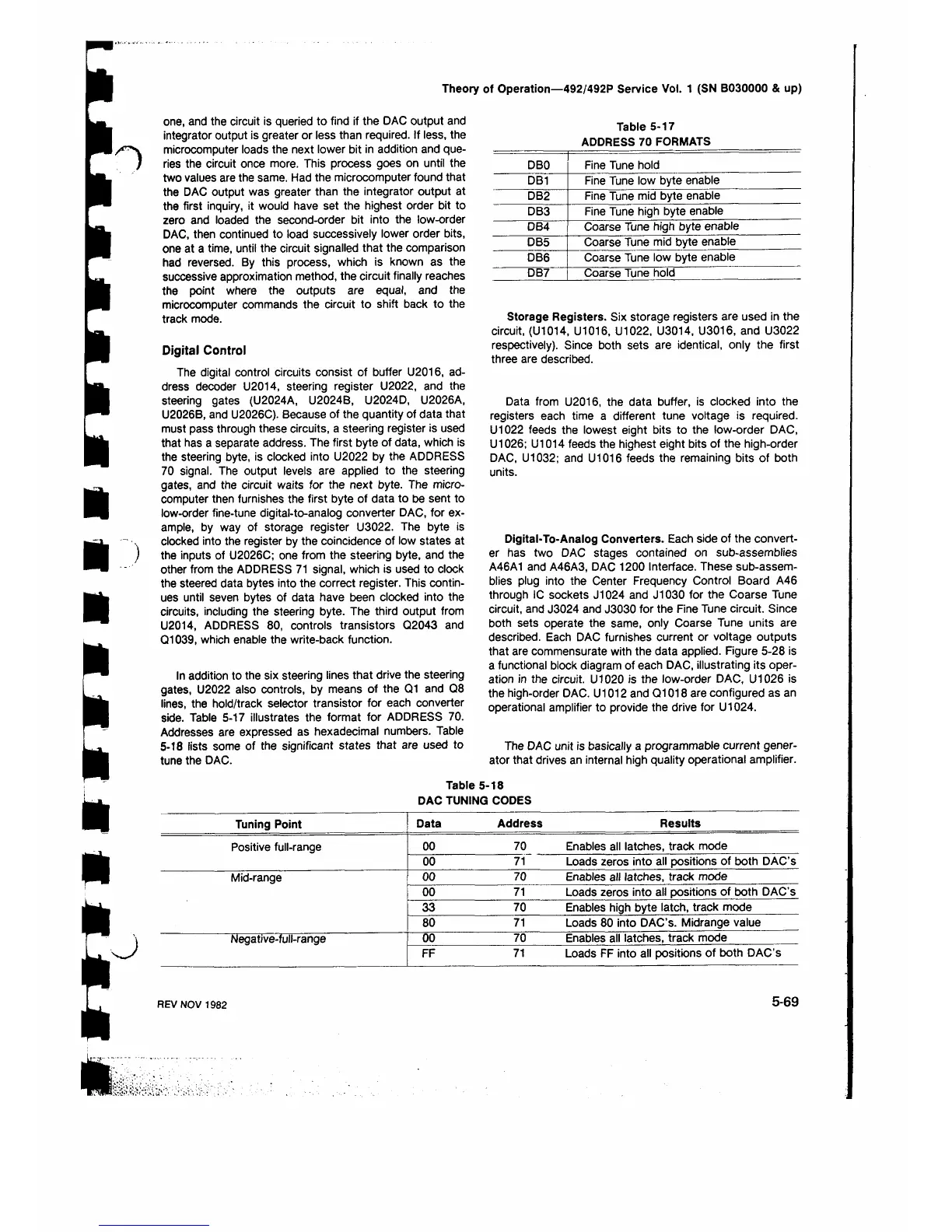
side. Table 5-17 illustrates the format for ADDRESS 70.
Addresses are expressed as hexadecimal numbers. Table
5-18 lists some of the significant states that are used to
tune the DAC.
Table 5-17
ADDRESS 70 FORMATS
DBO
Fine Tune hold
DB1 Fine Tune low byte enable
DB2
Fine Tune mid byte enable
DB3
Fine Tune high byte enable
DB4
Coarse Tune high byte enable
DB5
Coarse Tune mid byte enable
DB6
Coarse Tune low byte enable
DB7
Coarse Tune hold
Storage Registers. Six storage registers are used in the
circuit, (U1014, U1016, U1022, U3014, U3016, and U3022
respectively). Since both sets are identical, only the first
three are described.
Data from U2016, the data buffer, is clocked into the
registers each time a different tune voltage is required.
U1022 feeds the lowest eight bits to the low-order DAC,
U1026; U1014 feeds the highest eight bits of the high-order
DAC, U1032; and U1016 feeds the remaining bits of both
units.
Digital-To-Analog Converters. Each side of the convert
er has two DAC stages contained on sub-assemblies
A46A1 and A46A3, DAC 1200 Interface. These sub-assem
blies plug into the Center Frequency Control Board A46
through IC sockets J1024 and J1030 for the Coarse Tune
circuit, and J3024 and J3030 for the Fine Tune circuit. Since
both sets operate the same, only Coarse Tune units are
described. Each DAC furnishes current or voltage outputs
that are commensurate with the data applied. Figure 5-28 is
a functional block diagram of each DAC, illustrating its oper
ation in the circuit. U1020 is the low-order DAC, U1026 is
the high-order DAC. U1012 and Q1018 are configured as an
operational amplifier to provide the drive for U1024.
The DAC unit is basically a programmable current gener
ator that drives an internal high quality operational amplifier.
Table 5-18
DAC TUNING CODES
Tuning Point
Data Address
Results
Positive full-range
0 0 70 Enables all latches, track mode
0 0
71 Loads zeros into all positions of both DAC’s
Mid-range
0 0 70 Enables all latches, track mode
0 0
71 Loads zeros into all positions of both DAC’s
33
70 Enables high byte latch, track mode
80
71
Loads 80 into DAC’s. Midrange value
Negative-full-range
0 0 70
Enables all latches, track mode
FF
71
Loads FF into all positions of both DAC’s
REV NOV 1982
5-69


 To Next Page
 Loading...