Theory of Operation—492/492P Service Vol. 1 (SN B030000 & up)
If, in the example shown earlier, the high-order device is
at point A in Fig. 5-27, incrementing the device to point B
has no effect on the output. If the MSB of the low-order
device is set to zero, as shown in the first example, the
combined output will actually decrease. Ordinarily, the Cen
ter Frequency Control circuit can increment and decrement
whenever the microcomputer commands without going
through a special routine. However, as just described, some
microcomputer adjustment is necessary to compensate for
the disparity that usually occurs between the low-order and
high-order DAC units.
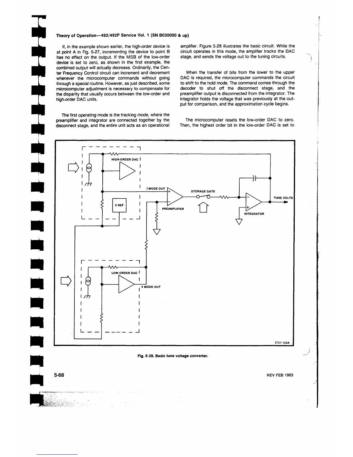
The first operating mode is the tracking mode, where the
preamplifier and integrator are connected together by the
disconnect stage, and the entire unit acts as an operational
amplifier. Figure 5-28 illustrates the basic circuit. While the
circuit operates in this mode, the amplifier tracks the DAC
stage, and sends the voltage out to the tuning circuits.
When the transfer of bits from the lower to the upper
DAC is required, the microcomputer commands the circuit
to shift to the hold mode. The command comes through the
decoder to shut off the disconnect stage, and the
preamplifier output is disconnected from the integrator. The
integrator holds the voltage that was previously at the out
put for comparison, and the approximation cycle begins.
The microcomputer resets the low-order DAC to zero.
Then, the highest order bit in the low-order DAC is set to
Fig. 5-28. Basic tune voltage converter.
5-68
REV FEB 1983



 To Next Page