Theory of Operation—492/492P Service Vol. 1 (SN B030000 & up)
Hex address Data path
74 Input to LED display shift registers and pow-
er-up circuit.
F4 Output from keyboard and frequency
encoders.
Input. DBO, DB1, DB2, and DB4 provide the inputs to
shift registers U2045, U3030, U5045, and U6075. The
microcomputer writes to this input port eight times to fill the
shift registers, which drive the front-panel LEDs. The MSB
of U6075 drives the graticule light circuit.
DB3 drives the power-up circuit.
Output. DBO through DB6 represent the 7-bit code from
the keyboard encoder. The code corresponds to one of the
positions shown in Fig. 5-39 under Switch Matrix Codes.
The X-Y positions of the switch can be decoded from the 7-
bit code as a decimal number in which the first digit is X and
the rest of the number is Y. To obtain the number:
1) convert the binary code to decimal number;
2 ) add 1 to the first digit and 1 to the second digit;
For example:
1) binary 0011101 is converted to decimal 29;
2 ) 1 is added to the first digit (2 ), and 1 is added to the
second digit (9), for X=3 and Y=10—the FINE button.
DB7 represents the direction of change in the FRE
QUENCY control (see FREQUENCY Encoder that follows).
Buffer U1047 is enabled only when the output path is
addressed.
Switch Encoding
A keyboard encoder, U3039, scans the switch matrix
continuously and compares any switch closures it senses
with those sensed during the last scan. Any new closure
causes the encoder to request service so the
microcomputer can read the code for the switch.
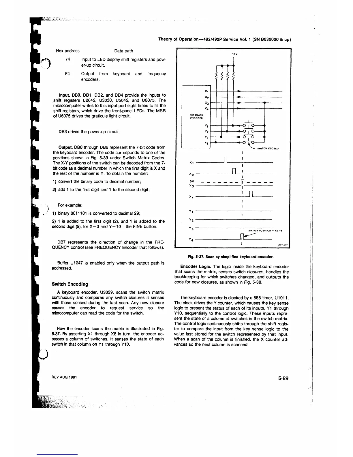
How the encoder scans the matrix is illustrated in Fig.
5-37. By asserting X1 through X8 in turn, the encoder ac
cesses a column of switches. It senses the state of each
switch in that column on Y1 through Y10.
Fig. 5-37. Scan by simplified keyboard encoder.
Encoder Logic. The logic inside the keyboard encoder
that scans the matrix, senses switch closures, handles the
bookkeeping for which switches changed, and outputs the
code for new closures, as shown in Fig. 5-38.
The keyboard encoder is clocked by a 555 timer, U1011.
The clock drives the Y counter, which causes the key sense
logic to present the status of each of its inputs, Y1 through
Y10, sequentially to the control logic. These inputs repre
sent the state of a column of switches in the switch matrix.
The control logic continuously shifts through the shift regis
ter to compare the input from the key sense logic to the
value last stored for the switch represented by that input.
When a scan of the column is finished, the X counter ad
vances so the next column is scanned.
REV AUG 1981
5-89



 To Next Page