Product: 492 Ser.1
Date: 2-25-85
Change Reference: C102/285
Table 4-4A
EQUIPMENT REQUIRED EOR ADJUSTING FIRST CONVERTER BIAS
AND START SPUR AMPLITUDE
Test Equipment |Characteristics
|Recommended Type
Digital Multimeter |</=10 uV to >/=350 Vdc
1
| TEKTRONIX DM502A and
|TM 500-Series Power Module
Sinewave Generator |2.0 MHz, O dBm
j+10 dBm to -lOO dBm
|TEKTRONIX SG503
1
Power Meter
|must measure 0 dBm
|Hewlett-Packard 435B
Power Sensor
| must measure 0 dBm
|@2 MHz
|Hewlett-Packard 8482A
1
Attenuator (13 dB)
1
|TEKTRONIX 2701
Coaxial Cable
1
|Tektronix Part No.
(50 ohm)
1
| 175-2765-00
Coaxial Cable
1
|Tektronix Part No.
(50 ohm)
1
| 175-2337-00
Coaxial Cable
1
|Tektronix Part No.
(50 ohm)
1
| 175-3310-00
1. Preparation
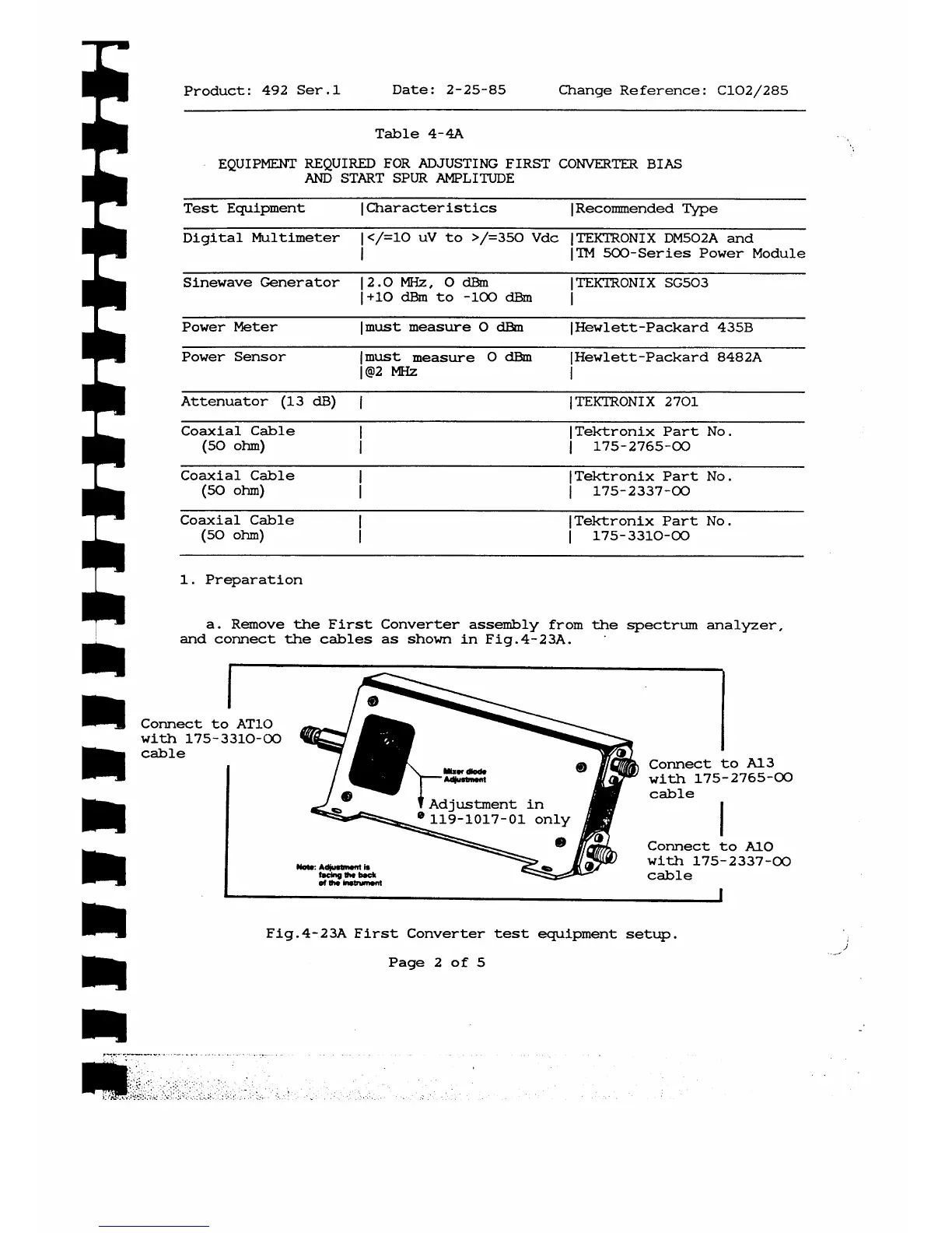
a. Remove the First Converter assembly from the spectrum analyzer,
and connect the cables as shown in Fig.4-23A.
Connect to ATIO
with 175-3310-00
cable
M o t·: A d j u itm n t i t
te e in g tf * b oc k
o f t h · in str um e nt
Connect to A13
with 175-2765-00
cable
Connect to AlO
with 175-2337-00
cable
Fig.4-23A First Converter test equipment setup.
Page 2 of 5



 To Next Page