Calibration—492/492P Service Vol. 1 (SN B030000 & up)
Performance Check
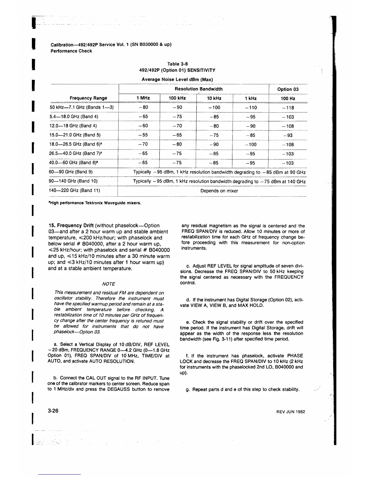
Table 3-8
492/492P (Option 01) SENSITIVITY
Average Noise Level dBm (Max)
Resolution Bandwidth
Option 03
Frequency Range
1 MHz
100 kHz
10 kHz
1 kHz
100 Hz
50 kHz—7.1 GHz (Bands 1—3) -8 0
-9 0
- 1 0 0
- 1 1 0
-118
5.4—18.0 GHz (Band 4) -6 5
-75
-85 -95
-103
12.0—18 GHz (Band 4) -6 0
-70
-80 -90
-108
15.0—21.0 GHz (Band 5) -5 5
-65
-75
-85
-93
18.0—26.5 GHz (Band 6 )a -7 0
-8 0
-90
- 1 0 0
-108
26.5—40.0 GHz (Band 7)a -65
-75
-85
-95
-103
40.0—60 GHz (Band 8 )a -65
-75
-85
-95 -103
60—90 GHz (Band 9)
Typically —95 dBm, 1 kHz resolution bandwidth degrading to -8 5 dBm at 90 GHz
90—140 GHz (Band 10)
Typically —95 dBm, 1 kHz resolution bandwidth degrading to —75 dBm at 140 GHz
140—220 GHz (Band 11)
Depends on mixer
‘ High performance Tektronix Waveguide mixers.
15. Frequency Drift (without phaselock—Option
03—and after a 2 hour warm up and stable ambient
temperature, <200 kHz/hour; with phaselock and
below serial # B040000, after a 2 hour warm up,
<25 kHz/hour; with phaselock and serial # B040000
and up, <15 kHz/10 minutes after a 30 minute warm
up; and <3 kHz/10 minutes after 1 hour warm up)
and at a stable ambient temperature.
NOTE
This measurement and residual FM are dependent on
oscillator stability. Therefore the instrument must
have the specified warmup period and remain at a sta
ble ambient temperature before checking. A
restabilization time of 10 minutes per GHz of frequen
cy change after the center frequency is retuned must
be allowed for instruments that do not have
phaselock—Option 03.
a. Select a Vertical Display of 10 dB/DIV, REF LEVEL
-20 dBm, FREQUENCY RANGE 0—4.2 GHz (0—1.8 GHz
Option 01), FREQ SPAN/DIV of 10 MHz, TIME/DIV at
AUTO, and activate AUTO RESOLUTION.
b. Connect the CAL OUT signal to the RF INPUT. Tune
one of the calibrator markers to center screen. Reduce span
to 1 MHz/div and press the DEGAUSS button to remove
any residual magnetism as the signal is centered and the
FREQ SPAN/DIV is reduced. Allow 10 minutes or more of
restabilization time for each GHz of frequency change be
fore proceeding with this measurement for non-option
instruments.
c. Adjust REF LEVEL for signal amplitude of seven divi
sions. Decrease the FREQ SPAN/DIV to 50 kHz keeping
the signal centered as necessary with the FREQUENCY
control.
d. If the instrument has Digital Storage (Option 02), acti
vate VIEW A, VIEW B, and MAX HOLD.
e. Check the signal stability or drift over the specified
time period. If the instrument has Digital Storage, drift will
appear as the width of the response less the resolution
bandwidth (see Fig. 3-11) after specified time period.
f. If the instrument has phaselock, activate PHASE
LOCK and decrease the FREQ SPAN/DIV to 10 kHz (2 kHz
for instruments with the phaselocked 2nd LO, B040000 and
up).
g. Repeat parts d and e of this step to check stability.
3-26
REV JUN 1982