21. Check LO Emission Out the RF INPUT (no more
than —10 dBm and less than —70 dBm for Option 01
instruments)
Two methods or procedures can be used to check EMI:
1) connect a sensitive power meter (see equipment list)
to the RF INPUT and directly measure the emitted
signal level; or
2 ) use a high frequency spectrum analyzer and connect
the RF INPUT to the RF INPUT of the analyzer under
test. Change the TIME/DIV of the analyzer under test
to MML.
22. Check Digital Storage (Option 02)
a. Set the front-panel controls as follows:
FREQUENCY 100 MHz
FREQ SPAN/DIV 10 MHz
RESOLUTION BANDWIDTH 1 MHz
Vertical Display 2 dB/DIV
REF LEVEL -12 dBm
RF ATTEN 20 dB
Digital Storage (Option 02) VIEW A
b. With the calibrator signal applied to the RF INPUT,
tune the signal to center screen while reducing the FREQ
SPAN/DIV to 200 kHz. Change the Vertical Display to
2 dB/DIV, then activate SAVE A.
b. Set the front-panel controls as follows:
Vertical Display LIN
FREQ SPAN/DIV 10 kHz
TIME/DIV 20 ms
RESOLUTION BANDWIDTH 1 MHz
REF LEVEL -30 dBm
Digital Storage (Option 02) VIEW A/VIEW B
c. Set the signal generator for a —30 dBm, 100 MHz
signal and tune the 492/492P FREQUENCY to center the
signal on screen.
d. Decrease the output of the signal generator so the
display is half screen, then modulate the signal with a 1 kHz
sine wave.
Calibration—492/492P Service Vol. 1 (SN B030000 & up)
Performance Check
e. Decrease the FREQ SPAN/DIV to 0. Adjust the FRE
QUENCY control if necessary to keep the signal centered.
f. Adjust the sine-wave generator output for a modula
tion amplitude of two divisions, then switch TRIGGERING to
INT.
g. Check the internal trigger operation through the 15 Hz
to 1 MHz frequency range.
c. Change the REF LEVEL to -1 0 dBm. Activate VIEW
B. Display B should be 2 dB below display A.
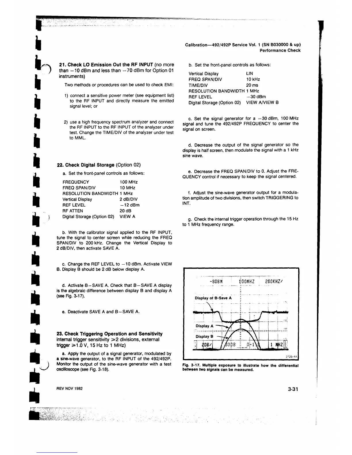
d. Activate B—SAVE A. Check that B—SAVE A display
is the algebraic difference between display B and display A
(see Fig. 3-17).
e. Deactivate SAVE A and B—SAVE A.
23. Check Triggering Operation and Sensitivity
internal trigger sensitivity > 2 divisions, external
trigger >1.0 V, 15 Hz to 1 MHz)
a. Apply the output of a signal generator, modulated by
a sine-wave generator, to the RF INPUT of the 492/492P.
Monitor the output of the sine-wave generator with a test
oscilloscope (see Fig. 3-18).
-80BN fOOKHZ 200KHZ/
Display of B-Save A ·
Fig. 3-17. Multiple exposure to illustrate how the differential
between two signals can be measured.
REV NOV 1982
3-31
 Loading...


