Calibration—492/492P Service Vol. 1 (SN B030000 & up)
Performance Check
NOTE
Because of deflection amplifier response, the display
amplitude will decrease at the high frequency end.
The triggering signal can also be applied through a
bnc-to-jack cable, to pins 1, 2 and 3 (see Fig. 3-25) of
the rear-panel ACCESSORIES connector (pin 2 is
Video in; pin 1 Ext Video select and pin 3 is ground).
Connect a jumper between pins 1 and 3.
h. Disconnect the test equipment. Apply, through a bnc
"T* connector and coaxial cable, the sine-wave generator
output to the EXT IN HORIZ/TRIG connector on the back
panel of the 492/492P (see Fig. 3-19). Monitor the input sig
nal amplitude with a test oscilloscope.
i. Set the sine-wave generator frequency to 1 kHz. Ad
just its output level for 2 V peak-to-peak (1.0 V peak) as
indicated on the test oscilloscope (see Fig. 3-20).
j. Change the 492/492P TIME/DIV to .2 s. Activate the
EXT Triggering.
k. Check that sweep runs as the generator frequency is
varied from 15 Hz to 1 MHz.
I. Return the TRIGGERING to FREE RUN and the input
signal level to 0 V.
24. Check External Sweep Operation (0 to 10 V
± 1 V should provide a full sweep across the 10
division graticule span)
a. With the test equipment connected as directed for the
previous step, change the TIME/DIV to EXT and deactivate
VIEW A/VIEW B.
b. Change the Vertical Display to 2 dB/DIV and position
the crt beam on the left graticule edge with the POSITION
control. This establishes the 0 V reference.
7000 Series
Test Oscilloscope
K.
--------------------------
71
<©>
©
©
J ® o ,
1111111
o
1®
0
0
I Vert . Input
Function
Generator
® n
o#R
•
®y§
° o
492 Spectrum Analyzer
•o?
:o:
7
!
o
1 /
RF Input
Modulated RF
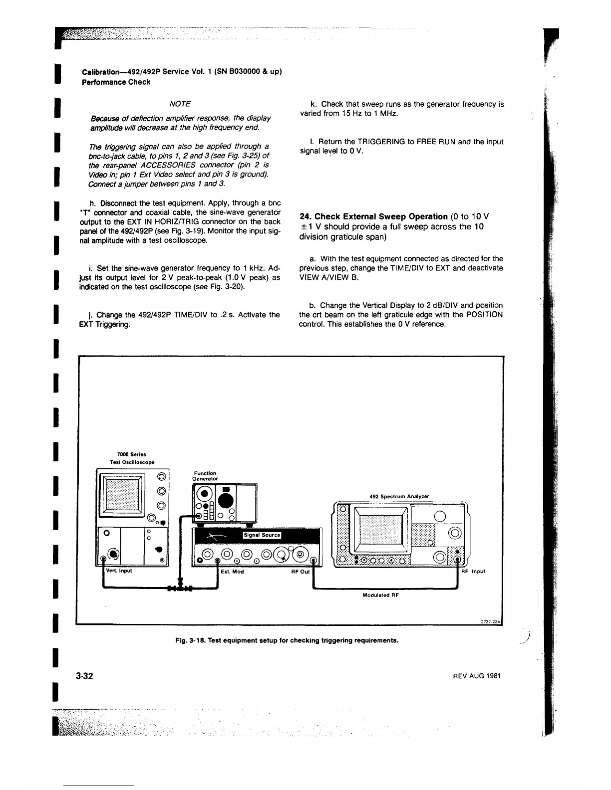
Fig. 3-18. Test equipment setup for checking triggering requirements.
3-32
REV AUG 1981
 Loading...


