Calibration—492/492P Service Vol. 1 (SN B030000 & up)
Performance Check
o
7000 Series
Test Oscilloscope
Function
Generator
p
©
© Θ
Ext. In (Horiz. Trig.)
o
® d
b Ο Θ Ο Ο O
0 0 c
X.
_
\ " '/ · I
.....
I
---
----
.
492 Rear Panel
I
a
o :
o
492 Spectrum Analyzer
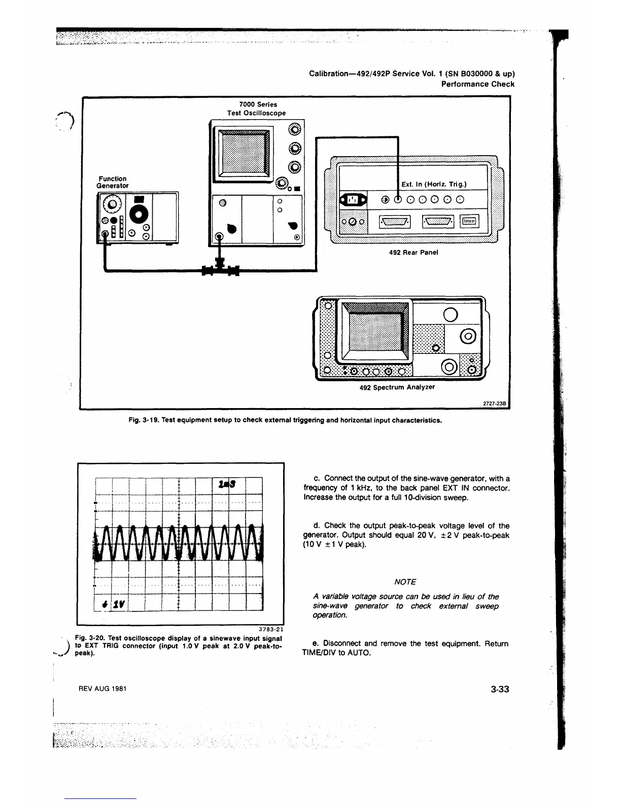
Fig. 3-19. Test equipment setup to check external triggering and horizontal input characteristics.
3 7 8 3 - 2 1
Fig. 3-20. Test oscilloscope display of a sinewave input signal
) to EXT TRIG connector (input 1.0 V peak at 2.0 V peak-to-
V peak).
c. Connect the output of the sine-wave generator, with a
frequency of 1 kHz, to the back panel EXT IN connector.
Increase the output for a full 1 0-division sweep.
d. Check the output peak-to-peak voltage level of the
generator. Output should equal 20 V, ± 2 V peak-to-peak
(10 V ±1 V peak).
NOTE
A variable voltage source can be used in lieu o f the
sine-wave generator to check external sweep
operation.
e. Disconnect and remove the test equipment. Return
TIME/DIV to AUTO.
REV AUG 1981
3-33
 Loading...


