Calibration—492/492P Service Vol. 1 (SN B030000 & up)
Adjustment Procedure
Digital
Multimeter
Function
Generator
®
o o o
OO
o
(?)
0 #o
• □ o
o o
□ o
Time Mark
Generator
Partial of 492 Back Panel showing J104 Accessory Connector
Test Oscilloscope
9
Vert In
BNC T-Connector
• ·
o
Ext Video In
BNC to pln-jack adapter
io o o
492 Spectrum Analyzer
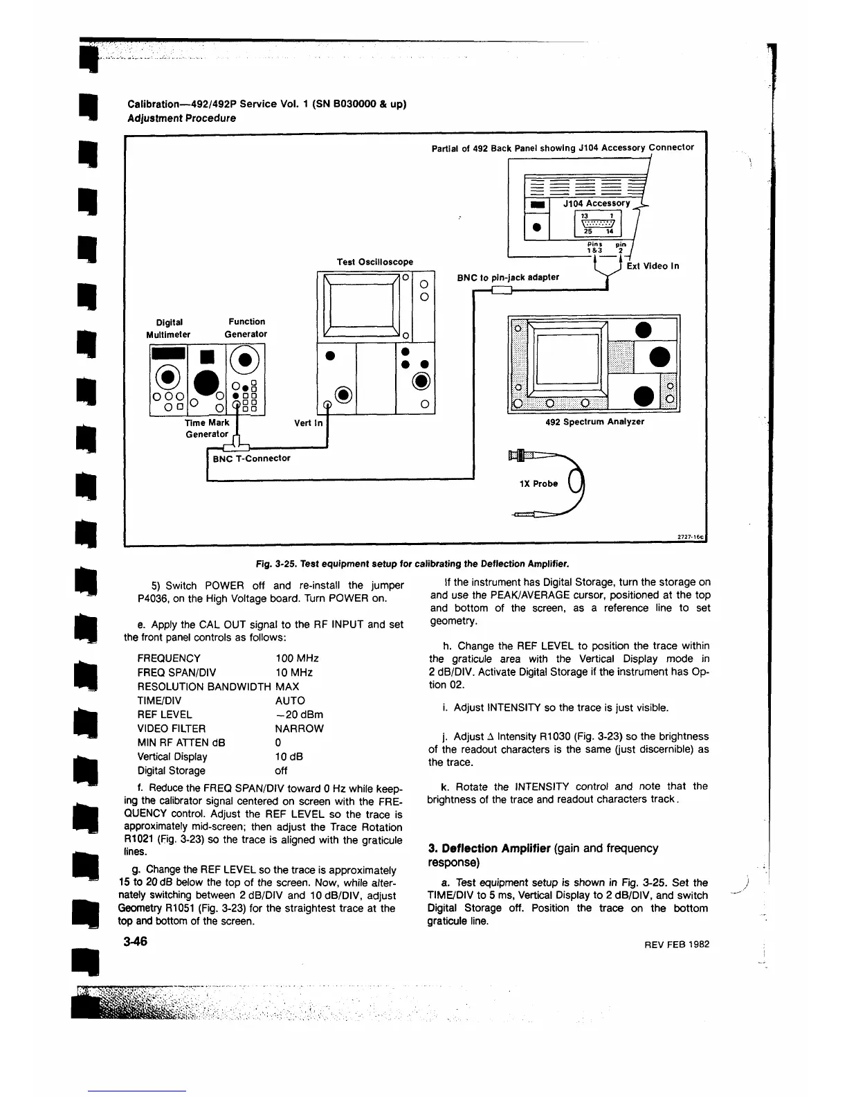
Fig. 3-25. Test equipment setup for calibrating the Deflection Amplifier.
5) Switch POWER oft and re-install the jumper
P4036, on the High Voltage board. Turn POWER on.
e. Apply the CAL OUT signal to the RF INPUT and set
the front panel controls as follows:
FREQUENCY 100 MHz
FREQ SPAN/DIV 10 MHz
RESOLUTION BANDWIDTH MAX
TIME/DIV AUTO
REF LEVEL -2 0 dBm
VIDEO FILTER NARROW
MIN RF ATTEN dB 0
Vertical Display 10 dB
Digital Storage off
f. Reduce the FREQ SPAN/DIV toward 0 Hz while keep
ing the calibrator signal centered on screen with the FRE
QUENCY control. Adjust the REF LEVEL so the trace is
approximately mid-screen; then adjust the Trace Rotation
R1021 (Fig. 3-23) so the trace is aligned with the graticule
lines.
g. Change the REF LEVEL so the trace is approximately
15 to 20 dB below the top of the screen. Now, while alter
nately switching between 2 dB/DIV and 10 dB/DIV, adjust
Geometry R1051 (Fig. 3-23) for the straightest trace at the
top and bottom of the screen.
3-46
If the instrument has Digital Storage, turn the storage on
and use the PEAK/AVERAGE cursor, positioned at the top
and bottom of the screen, as a reference line to set
geometry.
h. Change the REF LEVEL to position the trace within
the graticule area with the Vertical Display mode in
2 dB/DIV. Activate Digital Storage if the instrument has Op
tion 0 2 .
i. Adjust INTENSITY so the trace is just visible.
j. Adjust Λ Intensity R1030 (Fig. 3-23) so the brightness
of the readout characters is the same (just discernible) as
the trace.
k. Rotate the INTENSITY control and note that the
brightness of the trace and readout characters track.
3. Deflection Amplifier (gain and frequency
response)
a. Test equipment setup is shown in Fig. 3-25. Set the
TIME/DIV to 5 ms, Vertical Display to 2 dB/DIV, and switch
Digital Storage off. Position the trace on the bottom
graticule line.
REV FEB 1982
 Loading...


