f i
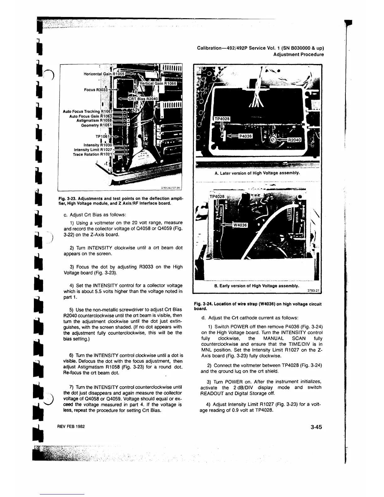
Auto Focus Tracking R1067
Auto Focus Gain R1063 =
Astigmatism R1058;
Geometry R1051 ■
l !
T.e,*|
Intensity R1030!
Intensity Limit R1027-
Trace Rotation R1021:·
X .I, ,1
3/S3-2&2’ 27-3Λ)
Fig. 3-23. Adjustments and test points on the deflection ampli
fier, High Voltage module, and Z Axis/RF Interface board.
c. Adjust Crt Bias as follows:
1) Using a voltmeter on the 20 volt range, measure
and record the collector voltage of Q4058 or Q4059 (Fig.
3-22) on the Z-Axis board.
2) Turn INTENSITY clockwise until a crt beam dot
appears on the screen.
3) Focus the dot by adjusting R3033 on the High
Voltage board (Fig. 3-23).
4) Set the INTENSITY control for a collector voltage
which is about 5.5 volts higher than the voltage noted in
part 1 .
5) Use the non-metallic screwdriver to adjust Crt Bias
R2040 counterclockwise until the crt beam is visible, then
turn the adjustment clockwise until the dot just extin
guishes, with the screen shaded. (If no dot appears with
the adjustment fully counterclockwise, this will be the
bias setting.)
6 ) Turn the INTENSITY control clockwise until a dot is
visible. Defocus the dot with the focus adjustment, then
adjust Astigmatism Ft 1058 (Fig. 3-23) for a round dot.
Re-focus the crt beam dot.
7) Turn the INTENSITY control counterclockwise until
the dot just disappears and again measure the collector
voltage of Q4058 or Q4059. Voltage should equal or ex
ceed the voltage measured in part 4. If the voltage is
less, repeat the procedure for setting Crt Bias.
Calibration—492/492P Service Vol. 1 (SN B030000 & up)
Adjustment Procedure
A. Later version of High Voltage assembly.
B. Early version of High Voltage assembly.
37 8 3 -2 7
Fig. 3-24. Location of wire strap (W4036) on high voltage circuit
board.
d. Adjust the Crt cathode current as follows:
1) Switch POWER off then remove P4036 (Fig. 3-24)
on the High Voltage board. Turn the INTENSITY control
fully clockwise, the MANUAL SCAN fully
counterclockwise and ensure that the TIME/DIV is in
MNL position. Set the Intensity Limit R1027 on the Z-
Axis board (Fig. 3-23) fully clockwise.
2) Connect the voltmeter between TP4028 (Fig. 3-24)
and the ground lug on the crt shield.
3) Turn POWER on. After the instrument initializes,
activate the 2 dB/DIV display mode and switch
READOUT and Digital Storage off.
4) Adjust Intensity Limit R1027 (Fig. 3-23) for a volt
age reading of 0.9 volt at TP4028.
REV FEB 1982
3-45
 Loading...


