g. Remove the line voltage regulator (Variac) and
reconnect the 492/492P directly to the power source.
2. CRT Display (Z-Axis board)
NOTE
Instruments prior to serial number B042200 do not
have Crt Bias adjustment R2040. If your instrument
does not have R2040, proceed to part b o f this step.
Auto Focus Tracking R1067 and Auto Focus Gain
R1063 no longer affect the display. They are set mid
range and not described in this procedure.
Calibration—492/492P Service Vol. 1 (SN B030000 & up)
Adjustment Procedure
a. Switch POWER off and preset the INTENSITY control
fully counterclockwise, MANUAL SCAN to midrange, and
TIME/DIV to MNL. Set the Intensity Limit R1027 on the Z-
Axis board (Fig. 3-23) fully counterclockwise and Crt Bias
R2040 on the High Voltage board (Fig. 3-24) fully clockwise.
b. Switch POWER on and after the power-up state has
stabilized change the Vertical Display mode to 2 dB/DIV,
deactivate READOUT, and if the instrument has Option 02
turn Digital Storage off.
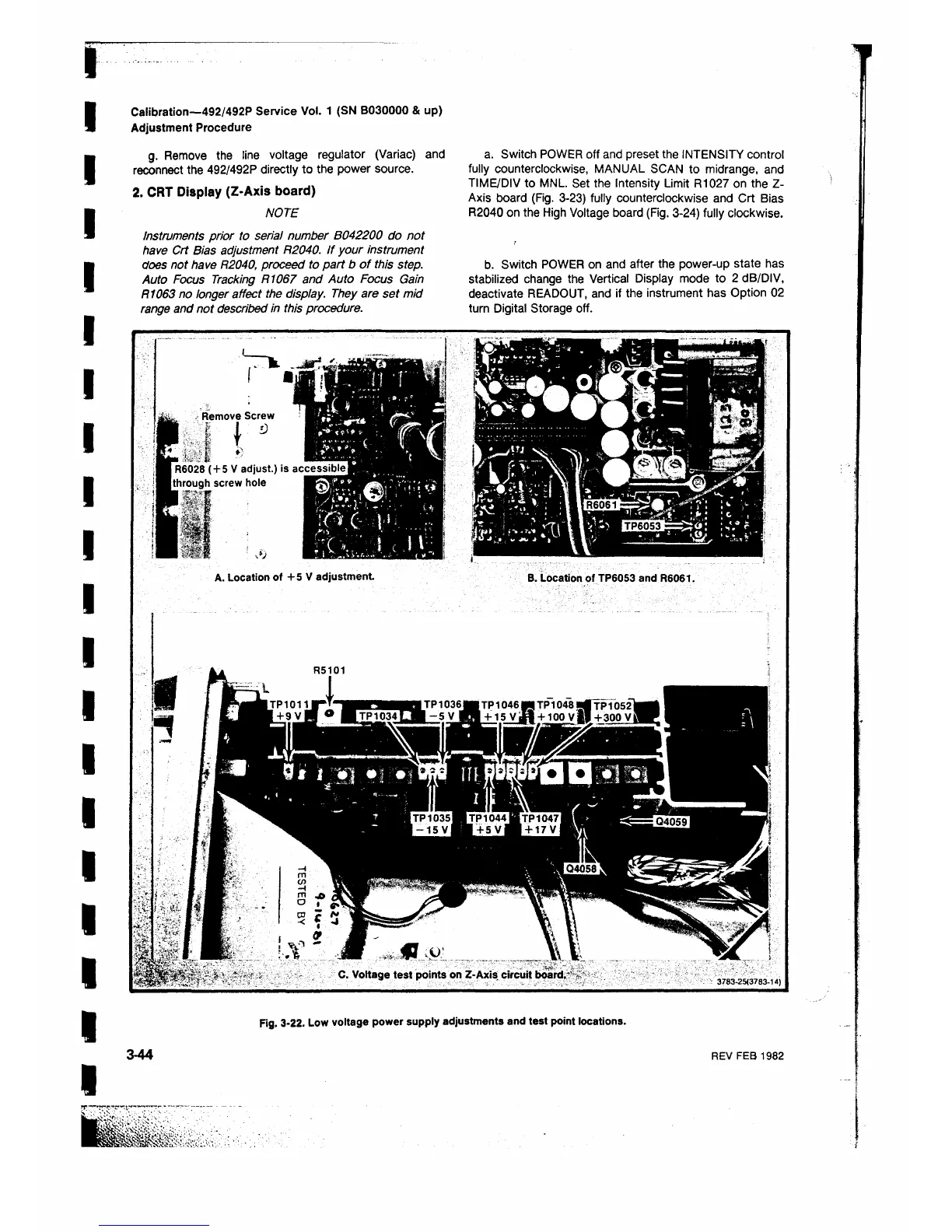
Remove Screw
,:ί t
I R6028 ( + 5 V adjust.) is
(through screw hole
i§
A. Location of + 5 V adjustment
B. Location of TP6053 and R6061.
C. Voltage test points on Z-Axis circuit board.-
3 7 8 3 - 2 5 ( 3 7 8 3- 1 4 )
Fig. 3-22. Low voltage power supply adjustments and test point locations.
 Loading...


