5. Calibrate the 1 st LO System and C enter
Frequency Control
An alternate procedure for the 492P is provided using
program control. Before proceeding with this step,
check sweep timing and amplitude accuracy.
a. Adjust Coarse Tuning Range
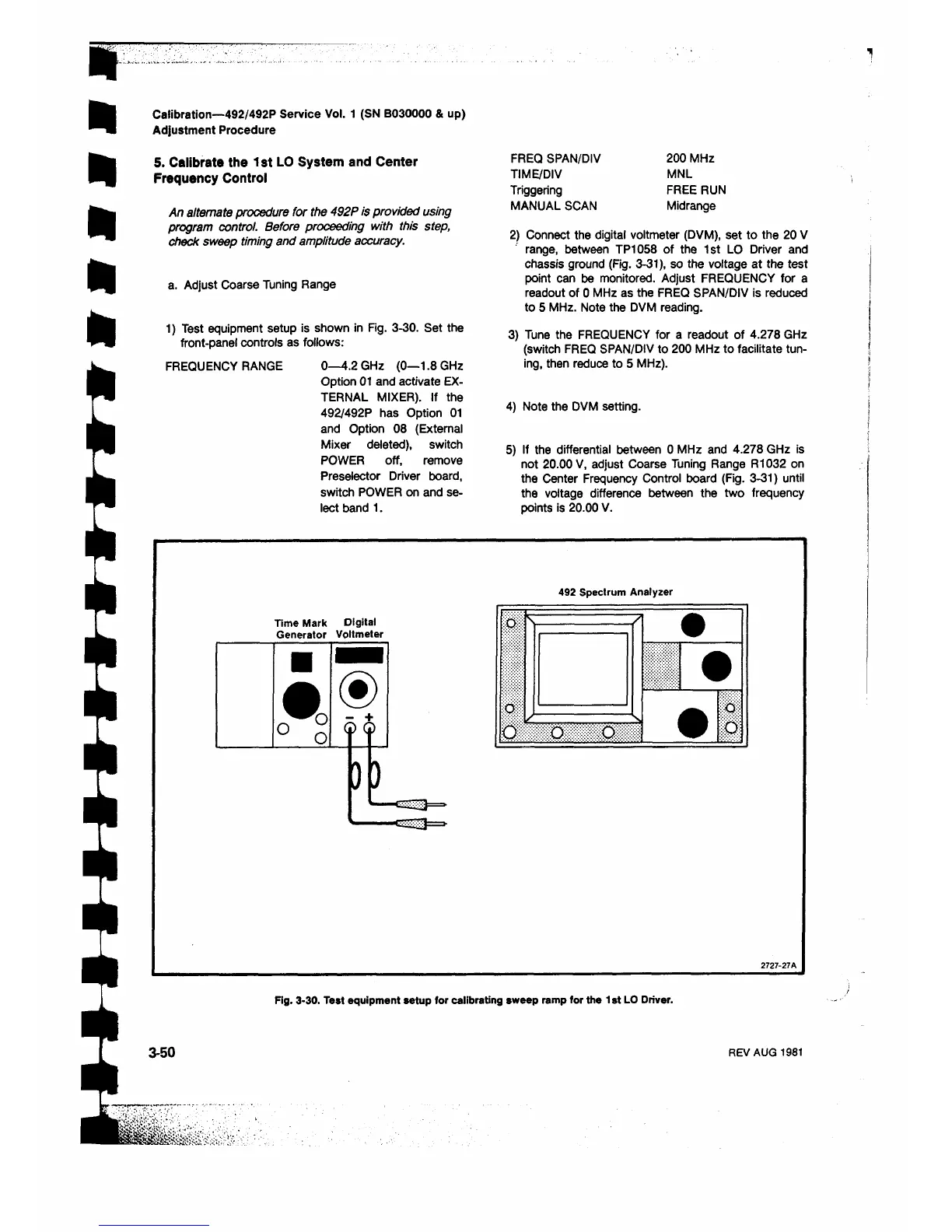
1) Test equipment setup is shown in Fig. 3-30. Set the
front-panel controls as follows:
FREQUENCY RANGE 0—4.2 GHz (0—1.8 GHz
Option 01 and activate EX
TERNAL MIXER). If the
492/492P has Option 01
and Option 08 (External
Mixer deleted), switch
POWER off, remove
Preselector Driver board,
switch POWER on and se
lect band 1 .
Calibration—492/492P Service Vol. 1 (SN B030000 & up)
Adjustment Procedure
FREQ SPAN/DIV 200 MHz
TIME/DIV MNL
Triggering FREE RUN
MANUAL SCAN Midrange
2) Connect the digital voltmeter (DVM), set to the 20 V
range, between TP1058 of the 1st LO Driver and
chassis ground (Fig. 3-31), so the voltage at the test
point can be monitored. Adjust FREQUENCY for a
readout of 0 MHz as the FREQ SPAN/DIV is reduced
to 5 MHz. Note the DVM reading.
3) Tune the FREQUENCY for a readout of 4.278 GHz
(switch FREQ SPAN/DIV to 200 MHz to facilitate tun
ing, then reduce to 5 MHz).
4) Note the DVM setting.
5) If the differential between 0 MHz and 4.278 GHz is
not 20.00 V, adjust Coarse Tuning Range R1032 on
the Center Frequency Control board (Fig. 3-31) until
the voltage difference between the two frequency
points is 20.00 V.
492 Spectrum Analyzer
Time Mark Digital
Generator Voltmeter
Fig. 3-30. Test equipment setup for calibrating sweep ramp for the 1st LO Driver.
3-50
REV AUG 1981
 Loading...


