1) Connect the DVM to TP1059, on the 1st LO Driver
(Fig. 3-31 A).
2) Adjust R1034 (Fig. 3-31 A) for -10.00 V).
c. Adjust Sweep Offset
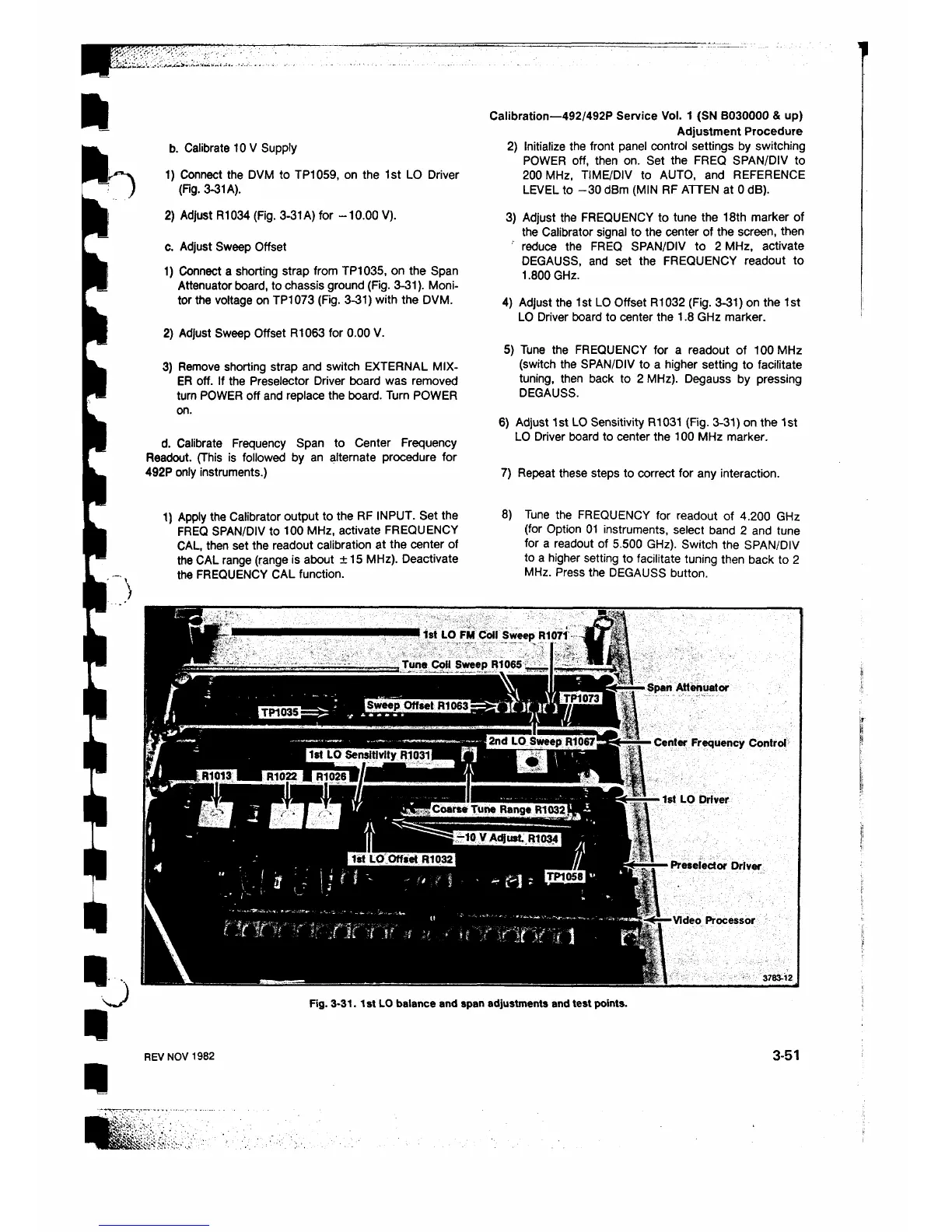
1) Connect a shorting strap from TP1035, on the Span
Attenuator board, to chassis ground (Fig. 3-31). Moni
tor the voltage on TP1073 (Fig. 3-31) with the DVM.
2) Adjust Sweep Offset R1063 for 0.00 V.
3) Remove shorting strap and switch EXTERNAL MIX
ER off. If the Preselector Driver board was removed
turn POWER off and replace the board. Turn POWER
on.
d. Calibrate Frequency Span to Center Frequency
Readout. (This is followed by an alternate procedure for
492P only instruments.)
b. Calibrate 10 V Supply
Calibration—492/492P Service Vol. 1 (SN B030000 & up)
Adjustment Procedure
2) Initialize the front panel control settings by switching
POWER off, then on. Set the FREQ SPAN/DIV to
200 MHz, TIME/DIV to AUTO, and REFERENCE
LEVEL to -30 dBm (MIN RF ATTEN at 0 dB).
3) Adjust the FREQUENCY to tune the 18th marker of
the Calibrator signal to the center of the screen, then
reduce the FREQ SPAN/DIV to 2 MHz, activate
DEGAUSS, and set the FREQUENCY readout to
1.800 GHz.
4) Adjust the 1st LO Offset R1032 (Fig. 3-31) on the 1st
LO Driver board to center the 1.8 GHz marker.
5) Tune the FREQUENCY for a readout of 100 MHz
(switch the SPAN/DIV to a higher setting to facilitate
tuning, then back to 2 MHz). Degauss by pressing
DEGAUSS.
6 ) Adjust 1st LO Sensitivity R1031 (Fig. 3-31) on the 1st
LO Driver board to center the 100 MHz marker.
7) Repeat these steps to correct for any interaction.
1) Apply the Calibrator output to the RF INPUT. Set the
FREQ SPAN/DIV to 100 MHz, activate FREQUENCY
CAL, then set the readout calibration at the center of
the CAL range (range is about +15 MHz). Deactivate
the FREQUENCY CAL function.
8 ) Tune the FREQUENCY for readout of 4.200 GHz
(for Option 01 instruments, select band 2 and tune
for a readout of 5.500 GHz). Switch the SPAN/DIV
to a higher setting to facilitate tuning then back to 2
MHz. Press the DEGAUSS button.
Fig. 3-31.1st LO balance and span adjustments and test points.
REV NOV 1982
3-51
 Loading...


