Calibration—492/492P Service Vol. 1 (SN B030000 & up)
Adjustment Procedure
c. Change the FREQUENCY RANGE control to the
15—21 GHz band. Adjust Bias 3 (R1026) for -0.25 V at
TP1011.
8. Baseline Leveling (Video Processor)
This procedure adjusts the baseline so band 4 response
perturbations are offset to level the display.
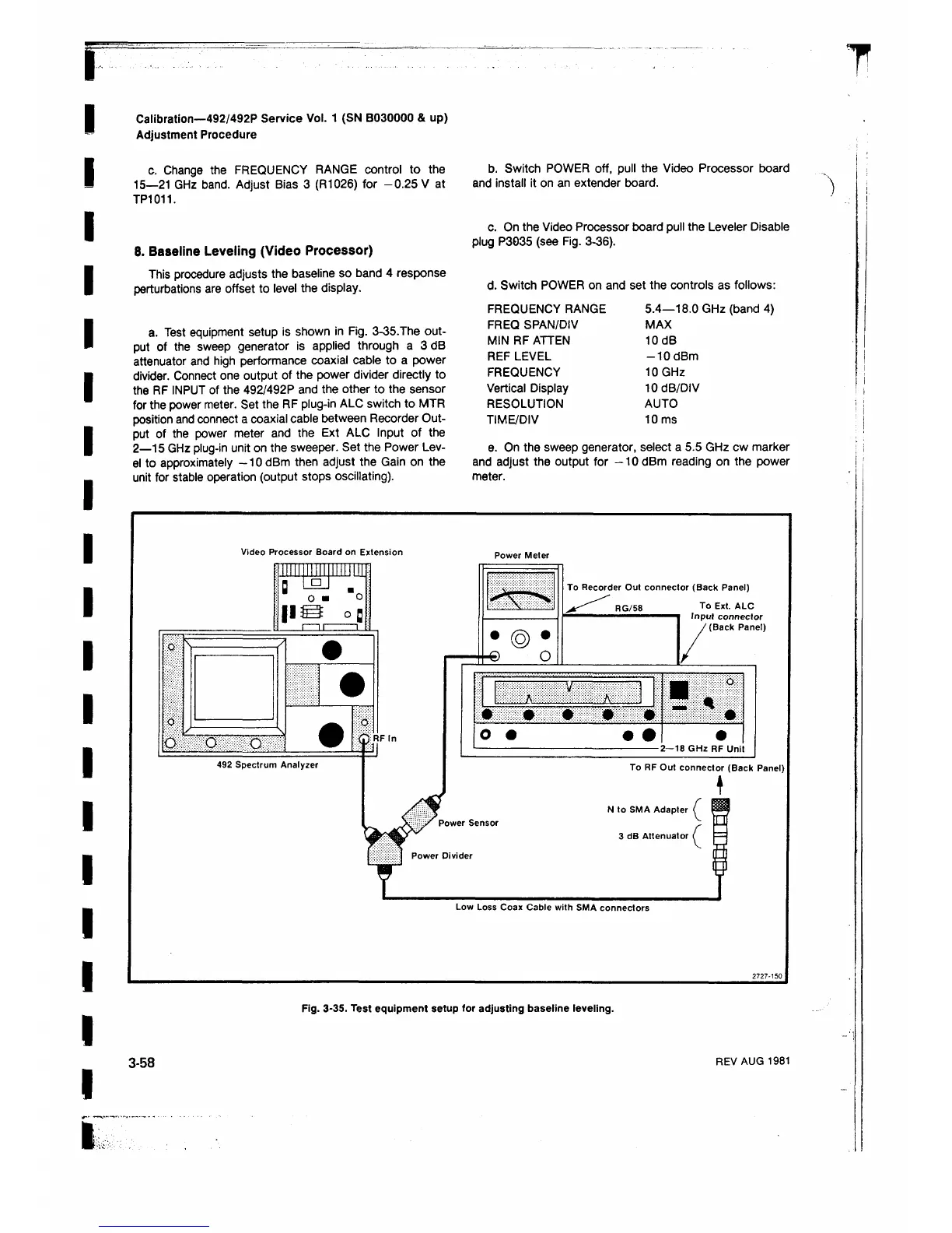
a. Test equipment setup is shown in Fig. 3-35.The out
put of the sweep generator is applied through a 3dB
attenuator and high performance coaxial cable to a power
divider. Connect one output of the power divider directly to
the RF INPUT of the 492/492P and the other to the sensor
for the power meter. Set the RF plug-in ALC switch to MTR
position and connect a coaxial cable between Recorder Out
put of the power meter and the Ext ALC Input of the
2— 15 GHz plug-in unit on the sweeper. Set the Power Lev
el to approximately -1 0 dBm then adjust the Gain on the
unit for stable operation (output stops oscillating).
b. Switch POWER off, pull the Video Processor board
and install it on an extender board.
c. On the Video Processor board pull the Leveler Disable
plug P3035 (see Fig. 3-36).
d. Switch POWER on and set the controls as follows:
FREQUENCY RANGE 5.4—18.0 GHz (band 4)
FREQ SPAN/DIV MAX
MIN RF ATTEN 10dB
REF LEVEL -1 0 dBm
FREQUENCY 10 GHz
Vertical Display 10 dB/DIV
RESOLUTION AUTO
TIME/DIV 10 ms
e. On the sweep generator, select a 5.5 GHz cw marker
and adjust the output for -10 dBm reading on the power
meter.
Fig. 3-35. Test equipment setup for adjusting baseline leveling.
3-58
REV AUG 1981
 Loading...


